How to Use Trimmer Potentiometer: Examples, Pinouts, and Specs

Introduction
A trimmer potentiometer, often referred to as a "trimpot," is a small, adjustable resistor used to fine-tune or calibrate circuits. It allows for precise control of resistance values, making it an essential component in applications where accuracy is critical. Trimmer potentiometers are typically adjusted using a small screwdriver and are designed for infrequent adjustments.
Explore Projects Built with Trimmer Potentiometer

Explore Projects Built with Trimmer Potentiometer
Common Applications and Use Cases
- Calibration of sensors and measurement devices
- Adjusting the gain in amplifiers
- Setting reference voltages in circuits
- Fine-tuning timing circuits
- Balancing bridge circuits
Technical Specifications
Below are the general technical specifications for a typical trimmer potentiometer. Note that specific values may vary depending on the model and manufacturer.
| Parameter | Specification |
|---|---|
| Resistance Range | 100 Ω to 1 MΩ (varies by model) |
| Tolerance | ±10% to ±20% |
| Power Rating | 0.1 W to 0.5 W |
| Adjustment Type | Single-turn or multi-turn |
| Operating Voltage | Up to 50 V (varies by model) |
| Operating Temperature | -55°C to +125°C |
| Lifespan | 200 to 1000 adjustment cycles |
Pin Configuration and Descriptions
Trimmer potentiometers typically have three pins. The configuration is as follows:
| Pin | Description |
|---|---|
| Pin 1 | One end of the resistive track (fixed resistance point) |
| Pin 2 | Wiper (adjustable resistance point) |
| Pin 3 | The other end of the resistive track (fixed resistance point) |
Note: The wiper (Pin 2) moves along the resistive track as the trimmer is adjusted, changing the resistance between Pin 1 and Pin 2 or between Pin 2 and Pin 3.
Usage Instructions
How to Use the Component in a Circuit
- Determine the Required Resistance Range: Select a trimmer potentiometer with a resistance range suitable for your application.
- Connect the Pins:
- Connect Pin 1 and Pin 3 to the circuit where the fixed resistance is required.
- Connect Pin 2 (wiper) to the point where the adjustable resistance is needed.
- Adjust the Resistance:
- Use a small screwdriver to turn the adjustment screw on the trimmer.
- Turning clockwise typically increases the resistance between Pin 1 and Pin 2 while decreasing the resistance between Pin 2 and Pin 3 (and vice versa).
- Test and Calibrate:
- Power on the circuit and measure the resistance or output to ensure proper calibration.
- Make fine adjustments as needed.
Important Considerations and Best Practices
- Avoid Over-Tightening: Do not force the adjustment screw beyond its limits, as this can damage the component.
- Power Rating: Ensure the trimmer's power rating is not exceeded to prevent overheating or failure.
- Stability: For applications requiring long-term stability, consider using multi-turn trimmers for finer adjustments.
- Mounting: Secure the trimmer properly on the PCB to prevent movement or damage during operation.
- ESD Precautions: Handle the component with care to avoid electrostatic discharge damage.
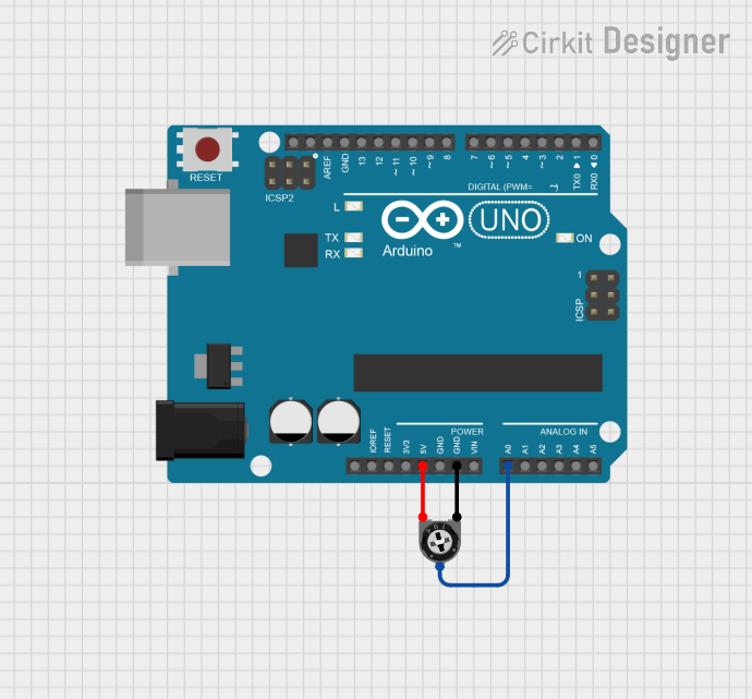
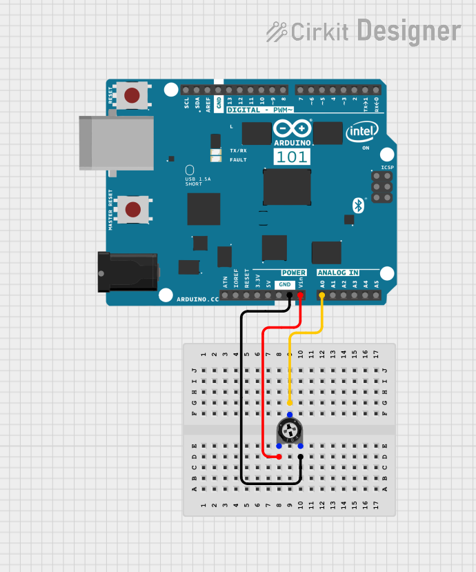
Example: Using a Trimmer Potentiometer with Arduino UNO
Below is an example of using a 10 kΩ trimmer potentiometer to adjust the brightness of an LED connected to an Arduino UNO.
// Example: Adjusting LED brightness using a trimmer potentiometer
// Connect the trimmer potentiometer as follows:
// - Pin 1 to GND
// - Pin 2 (wiper) to A0 (analog input on Arduino)
// - Pin 3 to 5V

const int potPin = A0;  // Analog pin connected to the trimmer potentiometer
const int ledPin = 9;   // PWM pin connected to the LED

void setup() {
  pinMode(ledPin, OUTPUT);  // Set LED pin as output
}

void loop() {
  int potValue = analogRead(potPin);  // Read the potentiometer value (0-1023)

  // Map the potentiometer value to a PWM range (0-255)
  int brightness = map(potValue, 0, 1023, 0, 255);

  analogWrite(ledPin, brightness);  // Adjust LED brightness
}
Troubleshooting and FAQs
Common Issues Users Might Face
No Change in Resistance:
- Cause: The adjustment screw is not being turned properly.
- Solution: Ensure you are using the correct screwdriver and apply gentle pressure while turning.
Component Overheating:
- Cause: The power rating of the trimmer is exceeded.
- Solution: Verify the power dissipation in the circuit and use a trimmer with a higher power rating if necessary.
Inconsistent Resistance:
- Cause: The trimmer is worn out or damaged.
- Solution: Replace the trimmer potentiometer with a new one.
Wiper Not Making Contact:
- Cause: Internal mechanical failure.
- Solution: Replace the component, as it cannot be repaired.
Solutions and Tips for Troubleshooting
- Always measure the resistance with a multimeter before and after installation to ensure proper functionality.
- If the trimmer potentiometer is not adjusting as expected, check for poor solder joints or loose connections.
- For critical applications, consider using sealed trimmer potentiometers to prevent dust or moisture from affecting performance.
By following this documentation, you can effectively use a trimmer potentiometer in your electronic projects for precise resistance adjustments and calibration.