How to Use Traffic LED module2: Examples, Pinouts, and Specs
Introduction
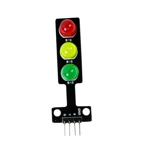
The Traffic LED Module2 is a versatile electronic component designed for signaling and traffic management applications. It features bright, high-visibility LEDs that can be used to indicate traffic conditions, directions, or warnings. This module is commonly employed in traffic lights, road signs, and other safety systems to enhance visibility and ensure smooth traffic flow. Its compact design and ease of integration make it suitable for both small-scale and large-scale projects.
Explore Projects Built with Traffic LED module2
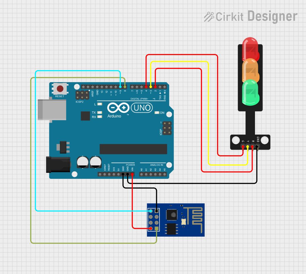
Explore Projects Built with Traffic LED module2
Common Applications
- Traffic light systems for intersections
- Pedestrian crossing signals
- Roadside warning signs
- Directional indicators in parking lots or construction zones
- Educational projects and prototyping
Technical Specifications
The following table outlines the key technical details of the Traffic LED Module2:
| Parameter | Value |
|---|---|
| Operating Voltage | 5V DC |
| Operating Current | 20mA per LED (typical) |
| LED Colors | Red, Yellow, Green |
| Dimensions | 30mm x 70mm x 10mm |
| Mounting Type | PCB-mounted or standalone |
| Control Method | Digital I/O pins or PWM |
Pin Configuration
The Traffic LED Module2 has a simple pinout for easy integration. The table below describes each pin:
| Pin | Name | Description |
|---|---|---|
| 1 | VCC | Power supply input (5V DC) |
| 2 | GND | Ground connection |
| 3 | RED | Control pin for the red LED |
| 4 | YELLOW | Control pin for the yellow LED |
| 5 | GREEN | Control pin for the green LED |
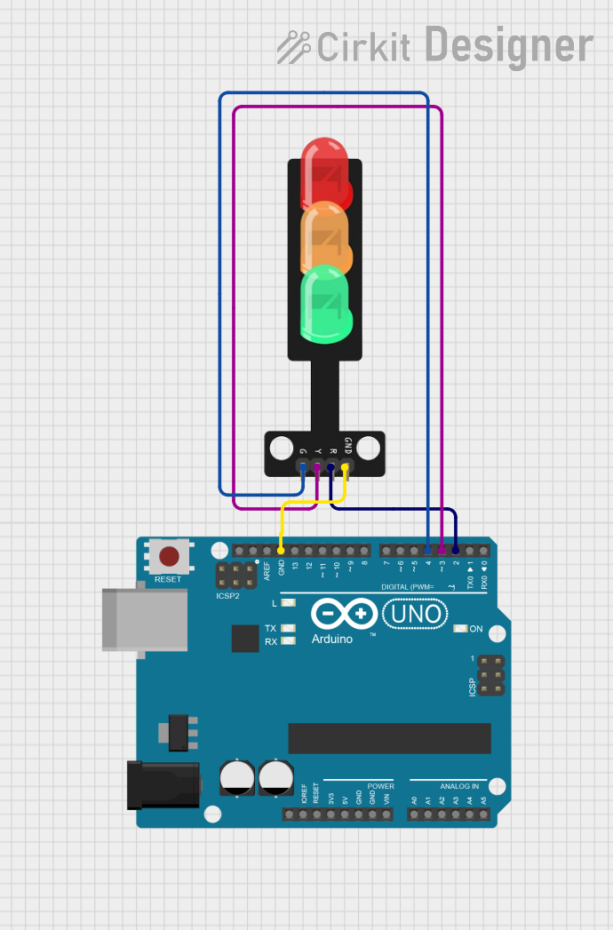
Usage Instructions
How to Use the Traffic LED Module2 in a Circuit
- Power Connection: Connect the
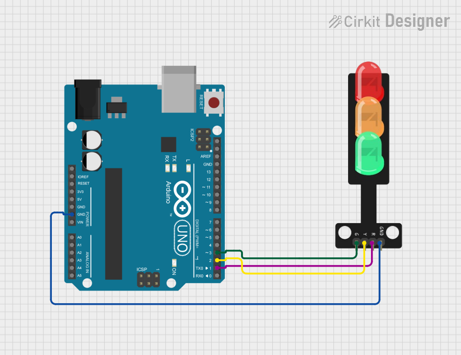
VCCpin to a 5V DC power source and theGNDpin to the ground of your circuit. - Control Pins: Use digital output pins from a microcontroller (e.g., Arduino UNO) to control the
RED,YELLOW, andGREENLEDs. Set the corresponding pin HIGH to turn on the LED and LOW to turn it off. - Resistors: It is recommended to use current-limiting resistors (e.g., 220Ω) in series with each control pin to prevent excessive current draw.
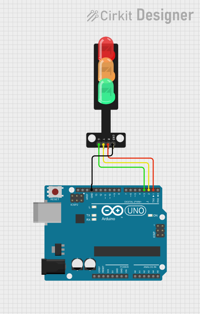
Example Arduino Code
Below is an example code snippet to control the Traffic LED Module2 using an Arduino UNO:
// Pin definitions for the Traffic LED Module2
const int redPin = 3;    // Connect to the RED pin of the module
const int yellowPin = 4; // Connect to the YELLOW pin of the module
const int greenPin = 5;  // Connect to the GREEN pin of the module

void setup() {
  // Set the LED pins as outputs
  pinMode(redPin, OUTPUT);
  pinMode(yellowPin, OUTPUT);
  pinMode(greenPin, OUTPUT);
}

void loop() {
  // Simulate a traffic light sequence

  // Turn on the green LED for 5 seconds
  digitalWrite(greenPin, HIGH);
  delay(5000); // Wait for 5 seconds
  digitalWrite(greenPin, LOW);

  // Turn on the yellow LED for 2 seconds
  digitalWrite(yellowPin, HIGH);
  delay(2000); // Wait for 2 seconds
  digitalWrite(yellowPin, LOW);

  // Turn on the red LED for 5 seconds
  digitalWrite(redPin, HIGH);
  delay(5000); // Wait for 5 seconds
  digitalWrite(redPin, LOW);
}
Best Practices
- Always use current-limiting resistors to protect the LEDs from overcurrent.
- Ensure the power supply provides a stable 5V DC to avoid damaging the module.
- Avoid exposing the module to extreme temperatures or moisture to maintain its longevity.
Troubleshooting and FAQs
Common Issues and Solutions
LEDs Not Lighting Up
- Cause: Incorrect wiring or insufficient power supply.
- Solution: Double-check the connections and ensure the
VCCandGNDpins are properly connected to a 5V power source.
LEDs Flickering
- Cause: Unstable power supply or loose connections.
- Solution: Use a regulated power supply and ensure all connections are secure.
One LED Not Working
- Cause: Faulty LED or control pin.
- Solution: Test the LED by connecting it directly to the power supply with a resistor. If it works, check the microcontroller's output pin.
Module Overheating
- Cause: Excessive current draw due to missing resistors.
- Solution: Always use appropriate current-limiting resistors in the circuit.
FAQs
Q: Can I use the Traffic LED Module2 with a 3.3V microcontroller?
A: Yes, but the brightness of the LEDs may be reduced. Ensure the control pins are compatible with 3.3V logic levels.
Q: Can I control the LEDs using PWM for brightness adjustment?
A: Yes, the module supports PWM control for dimming the LEDs. Use the analogWrite() function on Arduino to adjust brightness.
Q: Is the module waterproof?
A: No, the Traffic LED Module2 is not waterproof. Use a protective enclosure for outdoor applications.
Q: Can I use this module for AC-powered systems?
A: No, the module is designed for DC-powered systems only. Use a DC power supply for operation.