How to Use gps 7m: Examples, Pinouts, and Specs
Introduction
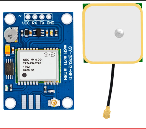
The GPS 7M is a compact and reliable GPS module designed to provide accurate location data with a typical accuracy of 7 meters. It is widely used in navigation, tracking, and geolocation applications. The module communicates using standard serial protocols, making it compatible with microcontrollers like Arduino, Raspberry Pi, and other embedded systems. Its small size and low power consumption make it ideal for portable and battery-powered devices.
Explore Projects Built with gps 7m


Explore Projects Built with gps 7m
Common Applications
- Vehicle tracking and navigation systems
- Drones and UAVs for location-based operations
- Personal tracking devices
- Geographic data logging
- IoT applications requiring geolocation
Technical Specifications
The GPS 7M module is equipped with a high-performance GPS receiver and supports various features for reliable operation.
Key Specifications
| Parameter | Value |
|---|---|
| GPS Receiver Type | 56-channel GPS receiver |
| Position Accuracy | 7 meters (typical) |
| Update Rate | 1 Hz (default), up to 10 Hz |
| Communication Protocol | UART (TTL level) |
| Baud Rate | 9600 bps (default) |
| Operating Voltage | 3.3V to 5V |
| Operating Current | 20 mA (typical) |
| Antenna Type | External active antenna |
| Dimensions | 25mm x 25mm x 8mm |
Pin Configuration
The GPS 7M module typically has a 4-pin interface for easy integration into circuits. Below is the pinout description:
| Pin Number | Pin Name | Description |
|---|---|---|
| 1 | VCC | Power supply input (3.3V to 5V) |
| 2 | GND | Ground connection |
| 3 | TX | Transmit data (UART output, 9600 bps default) |
| 4 | RX | Receive data (UART input, for configuration) |
Usage Instructions
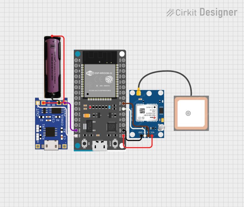
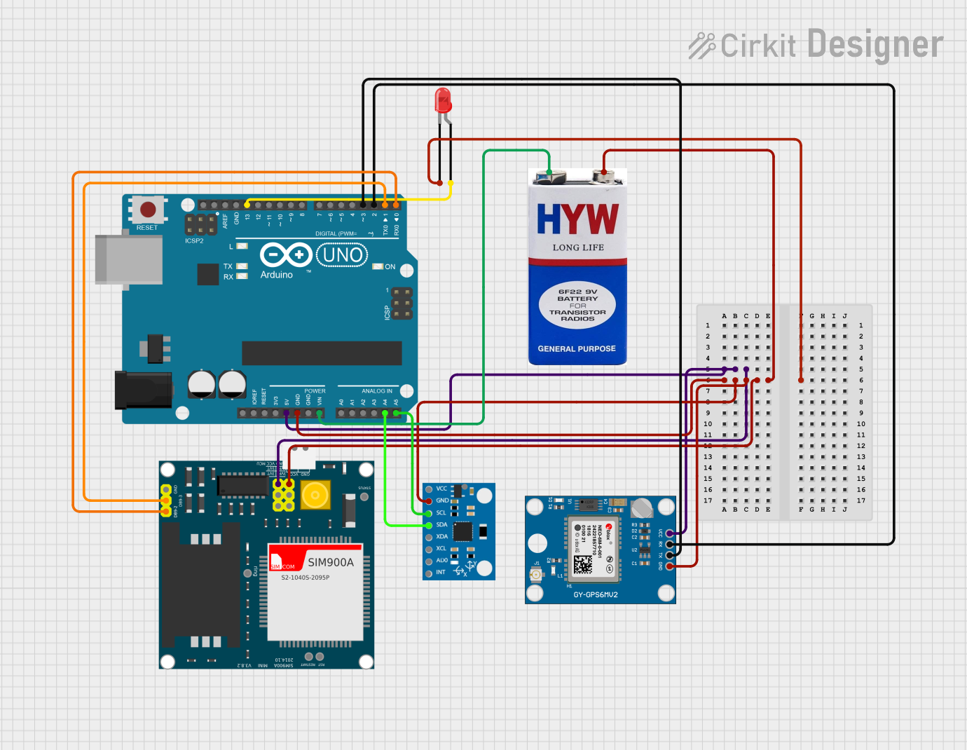
Connecting the GPS 7M to an Arduino UNO
To use the GPS 7M module with an Arduino UNO, follow these steps:
- Connect the VCC pin of the GPS module to the 5V pin on the Arduino.
- Connect the GND pin of the GPS module to the GND pin on the Arduino.
- Connect the TX pin of the GPS module to the Arduino's RX pin (digital pin 0).
- Connect the RX pin of the GPS module to the Arduino's TX pin (digital pin 1).
Sample Arduino Code
The following code demonstrates how to read GPS data from the GPS 7M module and display it on the Serial Monitor.
#include <SoftwareSerial.h>

// Define RX and TX pins for SoftwareSerial
SoftwareSerial gpsSerial(4, 3); // RX = pin 4, TX = pin 3

void setup() {
  Serial.begin(9600); // Initialize Serial Monitor at 9600 bps
  gpsSerial.begin(9600); // Initialize GPS module at 9600 bps

  Serial.println("GPS 7M Module Test");
  Serial.println("Waiting for GPS data...");
}

void loop() {
  // Check if data is available from the GPS module
  while (gpsSerial.available()) {
    char gpsData = gpsSerial.read(); // Read one character from GPS
    Serial.print(gpsData); // Print the character to Serial Monitor

    // Note: GPS data is in NMEA format. Parsing is required to extract
    // useful information like latitude, longitude, and time.
  }
}
Important Considerations
- Ensure the GPS module has a clear view of the sky for optimal satellite reception.
- Use an external active antenna for better signal strength in areas with weak GPS signals.
- Avoid placing the module near sources of electromagnetic interference (e.g., motors, power supplies).
- If using the module indoors, signal reception may be limited or unavailable.
Troubleshooting and FAQs
Common Issues and Solutions
No GPS data is received:
- Ensure the module is powered correctly (3.3V to 5V).
- Verify the TX and RX connections between the GPS module and the microcontroller.
- Check that the baud rate matches the module's default (9600 bps).
GPS data is incomplete or garbled:
- Ensure the GPS module has a clear view of the sky.
- Verify that the Serial Monitor and GPS module are set to the same baud rate.
- Check for loose or faulty connections.
Poor signal reception:
- Use an external active antenna for better signal strength.
- Avoid placing the module near metal objects or inside enclosures that block signals.
Module does not power on:
- Confirm that the power supply voltage is within the specified range (3.3V to 5V).
- Check for proper grounding and secure connections.
FAQs
Q: Can the GPS 7M module work indoors?
A: The GPS 7M module requires a clear view of the sky for optimal performance. While it may work indoors near windows, signal reception is generally weaker or unavailable indoors.
Q: How do I parse NMEA data from the GPS module?
A: NMEA data can be parsed using libraries like TinyGPS++ or by manually extracting fields from the NMEA sentences. These libraries simplify the process of obtaining latitude, longitude, and other information.
Q: Can I increase the update rate of the GPS module?
A: Yes, the update rate can be increased up to 10 Hz by sending specific configuration commands to the module. Refer to the module's datasheet for details.
Q: Is the GPS 7M compatible with 3.3V microcontrollers?
A: Yes, the GPS 7M module operates within a voltage range of 3.3V to 5V, making it compatible with both 3.3V and 5V systems.
By following this documentation, you can effectively integrate and use the GPS 7M module in your projects.