How to Use 24-Bit Analog-to-Digital Converter (ADC) for Weigh Scales: Examples, Pinouts, and Specs
Introduction
The HX711, manufactured by Avia Semiconductor, is a high-resolution 24-bit analog-to-digital converter (ADC) specifically designed for weigh scale applications. It is widely used in electronic scales and other precision measurement devices due to its ability to convert small analog signals from load cells into precise digital data. The HX711 integrates an amplifier and ADC in a compact package, simplifying the design of weigh scale systems.
Explore Projects Built with 24-Bit Analog-to-Digital Converter (ADC) for Weigh Scales
Explore Projects Built with 24-Bit Analog-to-Digital Converter (ADC) for Weigh Scales
Common Applications and Use Cases
- Digital weigh scales
- Industrial process control systems
- Force measurement devices
- Laboratory balances
- IoT-based weight monitoring systems
Technical Specifications
The HX711 is designed to interface directly with a bridge sensor (e.g., a load cell) and provides high accuracy and stability. Below are its key technical details:
Key Technical Details
- Resolution: 24-bit ADC
- Input Channels: 2 differential input channels (Channel A and Channel B)
- Programmable Gain: 128 or 64 for Channel A, fixed gain of 32 for Channel B
- Operating Voltage: 2.6V to 5.5V
- Current Consumption: < 1.5mA (normal operation), < 1µA (power-down mode)
- Data Rate: 10 Hz or 80 Hz
- Temperature Range: -40°C to +85°C
- Interface: Serial (2-wire interface: Data and Clock)
- Package: SOP-16
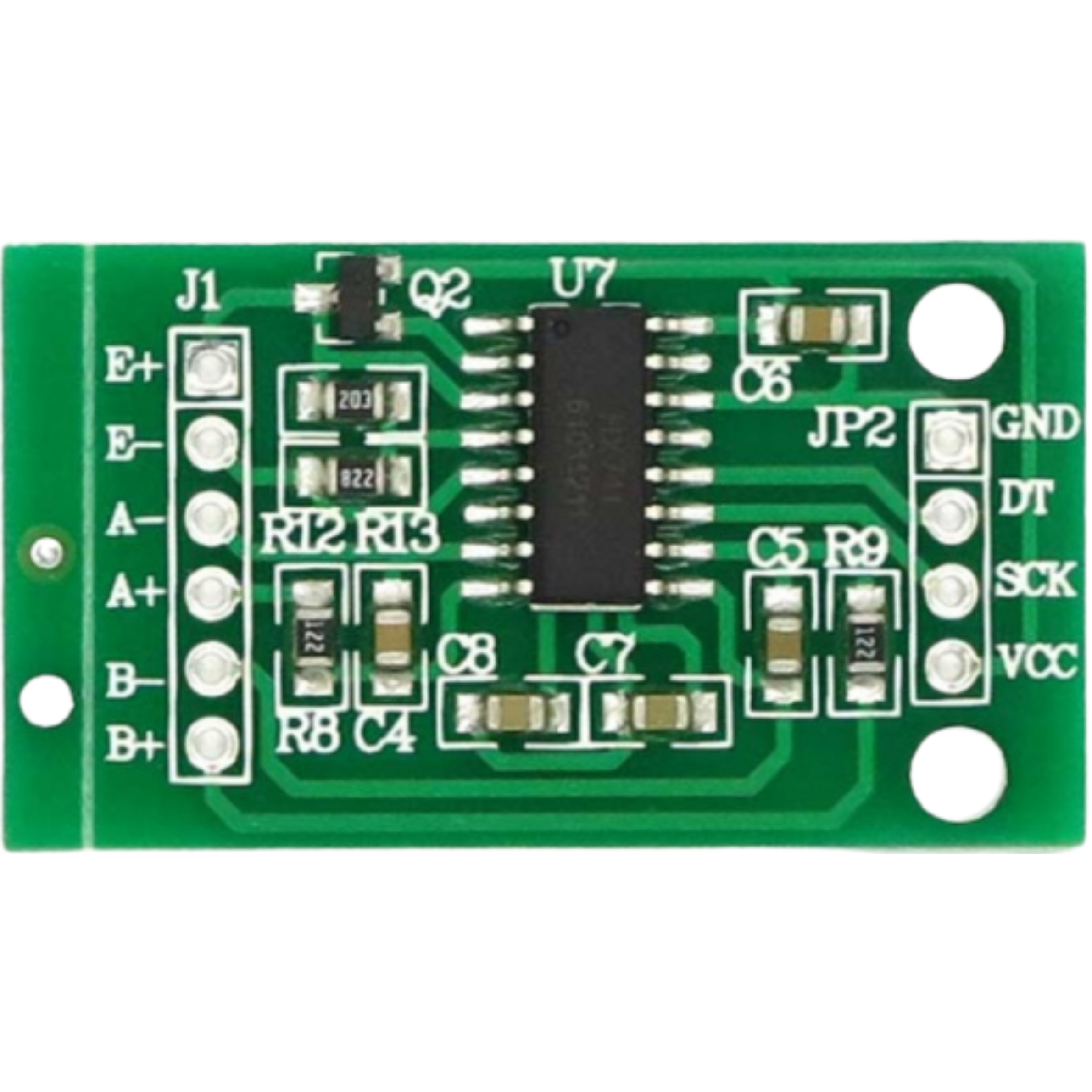
Pin Configuration and Descriptions
The HX711 has 16 pins, with the following configuration:
| Pin Number | Pin Name | Description |
|---|---|---|
| 1 | VCC | Power supply input (2.6V to 5.5V). |
| 2 | VFB | Feedback voltage for internal regulator. |
| 3 | BASE | Base voltage for internal regulator. |
| 4 | AVDD | Analog power supply. |
| 5 | AGND | Analog ground. |
| 6 | BGND | Bridge ground (connect to load cell ground). |
| 7 | B- | Negative input for the load cell. |
| 8 | B+ | Positive input for the load cell. |
| 9 | RATE | Data output rate selection (connect to GND for 10 Hz, VCC for 80 Hz). |
| 10 | DGND | Digital ground. |
| 11 | DOUT | Serial data output. |
| 12 | PD_SCK | Power-down and serial clock input. |
| 13 | VBG | Bandgap reference voltage. |
| 14 | AVDD | Analog power supply (duplicate pin). |
| 15 | VFB | Feedback voltage for internal regulator (duplicate pin). |
| 16 | VCC | Power supply input (duplicate pin). |
Usage Instructions
The HX711 is straightforward to use in a circuit, especially for applications involving load cells. Below are the steps and considerations for using the HX711:
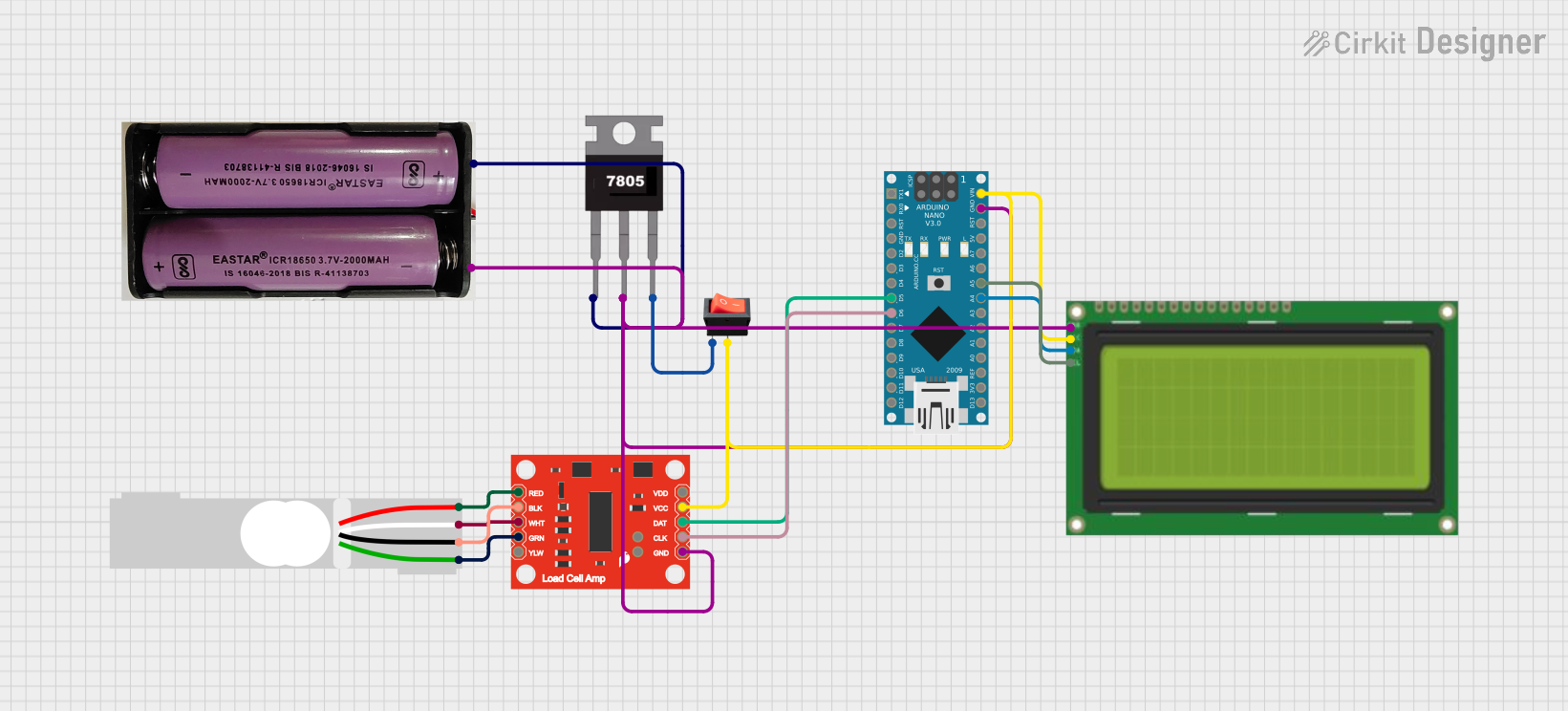
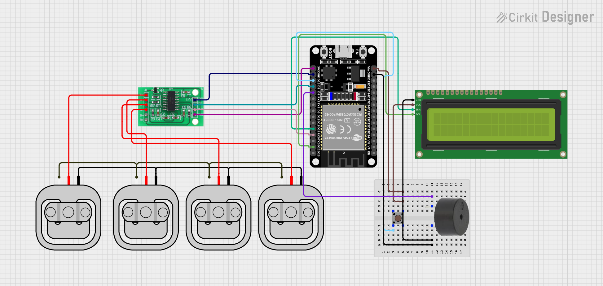
Connecting the HX711 to a Load Cell
- Power Supply: Connect the VCC pin to a 2.6V–5.5V power source and the GND pins (AGND, DGND, BGND) to ground.
- Load Cell Connection:
- Connect the positive and negative excitation wires of the load cell to the B+ and B- pins, respectively.
- Connect the positive and negative signal wires of the load cell to the A+ and A- pins (Channel A).
- Data and Clock Pins:
- Connect the DOUT pin to a microcontroller's digital input pin.
- Connect the PD_SCK pin to a microcontroller's digital output pin.
- Data Rate Selection: Connect the RATE pin to GND for a 10 Hz data rate or to VCC for an 80 Hz data rate.
Important Considerations and Best Practices
- Use decoupling capacitors (e.g., 0.1µF and 10µF) between VCC and GND to reduce noise.
- Ensure proper grounding to avoid measurement errors.
- Use shielded cables for the load cell to minimize interference.
- Calibrate the system to account for load cell sensitivity and offset.
Example Code for Arduino UNO
Below is an example of how to interface the HX711 with an Arduino UNO to read weight data:
#include "HX711.h" // Include the HX711 library

// Define pins for HX711
#define DOUT  3  // Data output pin connected to Arduino pin 3
#define CLK   2  // Clock pin connected to Arduino pin 2

HX711 scale; // Create an instance of the HX711 class

void setup() {
  Serial.begin(9600); // Initialize serial communication at 9600 baud
  scale.begin(DOUT, CLK); // Initialize the HX711 with the defined pins

  // Perform calibration (adjust the scale factor as needed)
  Serial.println("Calibrating... Place a known weight on the scale.");
  delay(5000); // Wait for 5 seconds to stabilize
  scale.set_scale(2280.f); // Set the scale factor (adjust based on calibration)
  scale.tare(); // Reset the scale to zero
  Serial.println("Calibration complete.");
}

void loop() {
  // Read weight data from the HX711
  float weight = scale.get_units(10); // Average 10 readings for stability
  Serial.print("Weight: ");
  Serial.print(weight);
  Serial.println(" kg"); // Display weight in kilograms

  delay(1000); // Wait 1 second before the next reading
}
Notes on the Code
- The
HX711.hlibrary must be installed in the Arduino IDE. You can install it via the Library Manager. - Adjust the scale factor (
2280.fin the example) based on your load cell's specifications and calibration process.
Troubleshooting and FAQs
Common Issues and Solutions
No Data Output:
- Ensure the DOUT and PD_SCK pins are correctly connected to the microcontroller.
- Verify that the HX711 is powered and the load cell is properly connected.
Unstable or Noisy Readings:
- Use proper grounding and shielding for the load cell wires.
- Add decoupling capacitors to the power supply lines.
- Ensure the load cell is not subjected to vibrations or external forces.
Incorrect Weight Measurements:
- Perform proper calibration using a known weight.
- Check the load cell's wiring and ensure it matches the HX711's input configuration.
Device Not Responding:
- Verify the power supply voltage is within the specified range (2.6V–5.5V).
- Check the connections for loose or broken wires.
FAQs
Q1: Can the HX711 be used with a 3.3V microcontroller?
A1: Yes, the HX711 operates within a voltage range of 2.6V to 5.5V, making it compatible with 3.3V systems.
Q2: How do I calibrate the HX711?
A2: Use a known weight to determine the scale factor. Adjust the scale factor in your code until the output matches the known weight.
Q3: Can I use both input channels (A and B) simultaneously?
A3: Yes, but note that Channel A has a programmable gain (128 or 64), while Channel B has a fixed gain of 32. Channel A is typically used for higher precision measurements.
Q4: What is the maximum weight the HX711 can measure?
A4: The maximum weight depends on the load cell's capacity, not the HX711 itself. Ensure the load cell's output voltage remains within the HX711's input range.
By following this documentation, you can effectively integrate the HX711 into your weigh scale or precision measurement project.