Cirkit Designer Logo
Cirkit Designer
Your all-in-one circuit design IDE
Home / 
Component Documentation

How to Use Trubilty sensor: Examples, Pinouts, and Specs

Image of Trubilty sensor
Cirkit Designer LogoDesign with Trubilty sensor in Cirkit Designer

Introduction

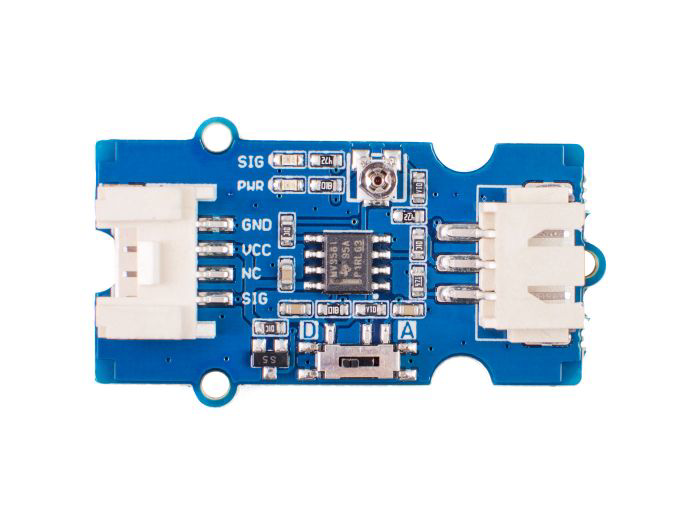
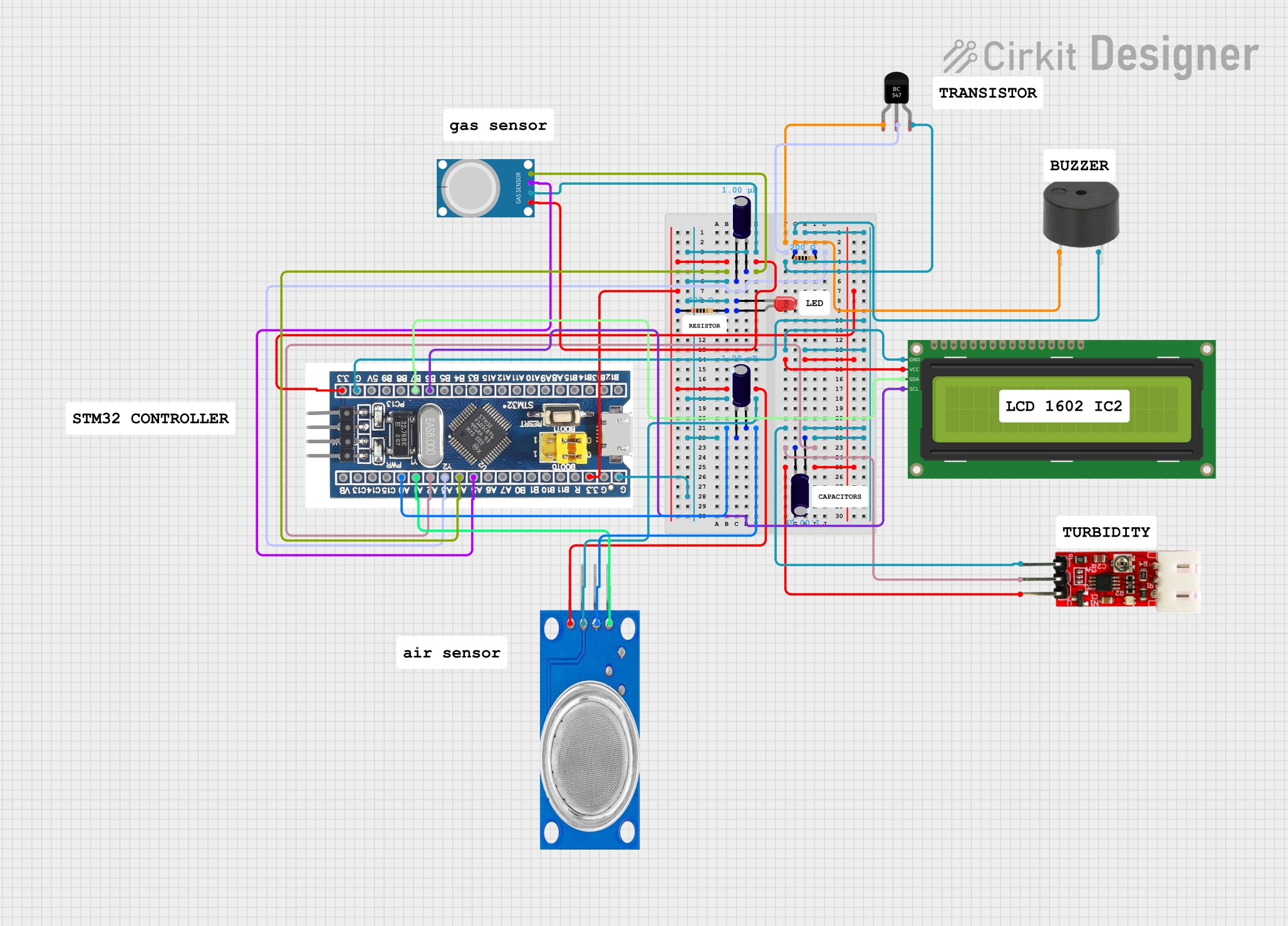
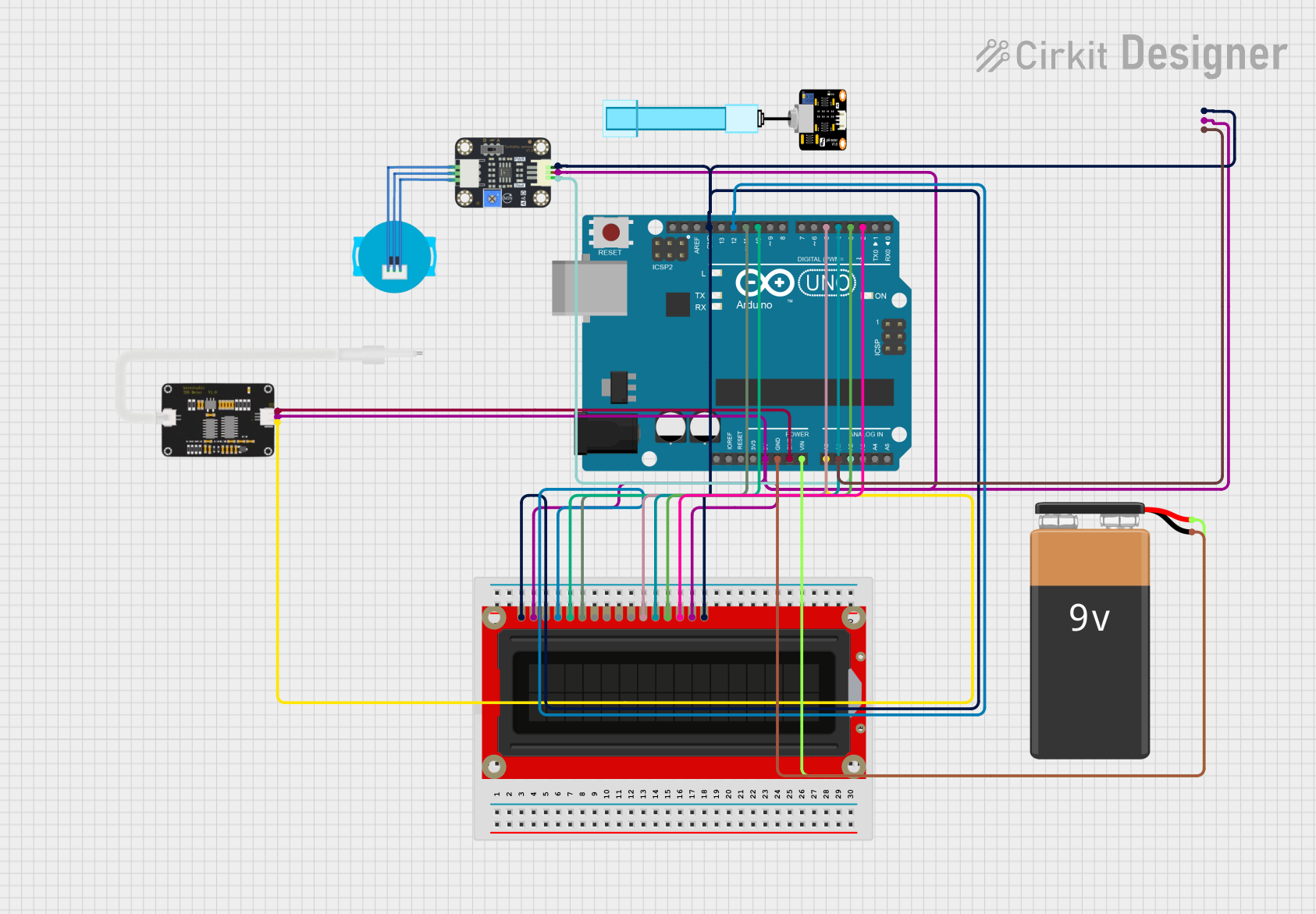
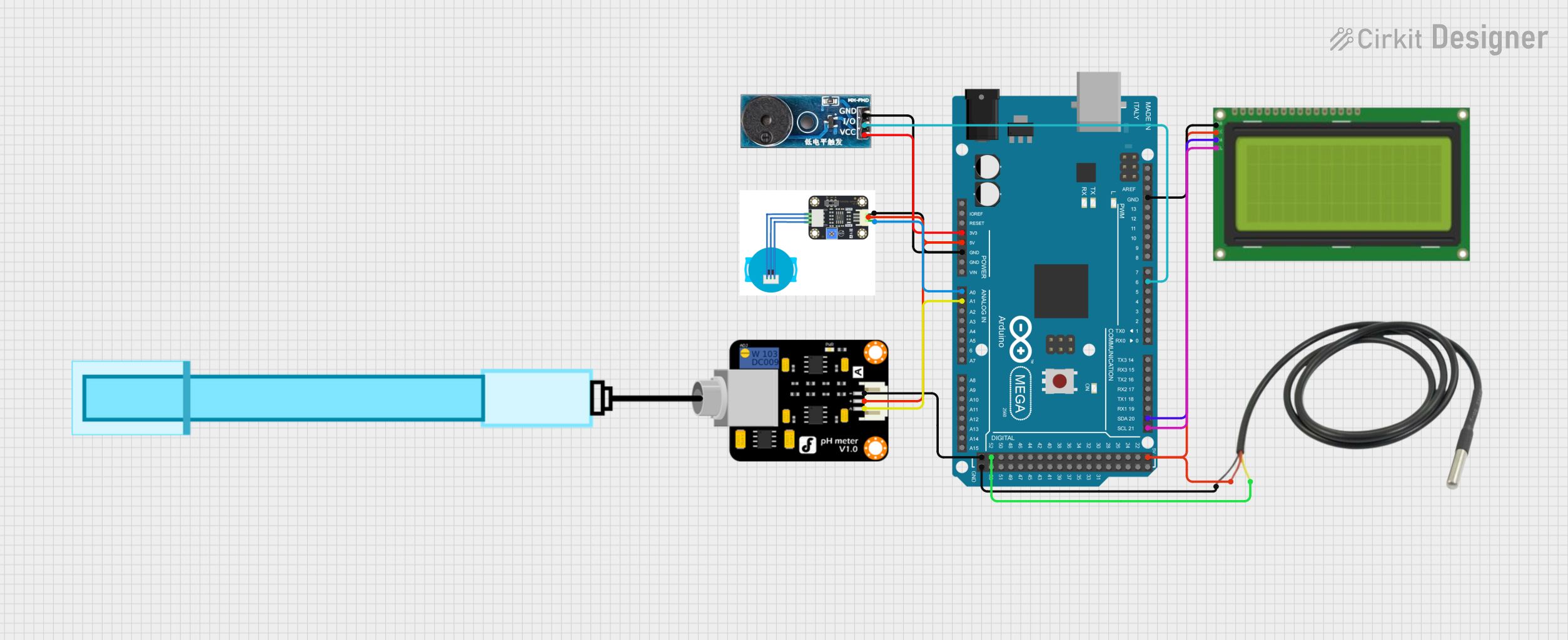
The Grove Turbidity Sensor is an electronic device designed to measure the turbidity, or cloudiness, of a fluid. It operates by emitting light and detecting the light that is scattered by particles suspended in the fluid. This sensor is an essential tool for assessing water quality in various applications, including water treatment plants, aquariums, and environmental monitoring systems.

Explore Projects Built with Trubilty sensor

Use Cirkit Designer to design, explore, and prototype these projects online. Some projects support real-time simulation. Click "Open Project" to start designing instantly!
Arduino GIGA R1 WIFI Turbidity Monitoring System
Image of TurbidShower: A project utilizing Trubilty sensor in a practical application
This circuit is designed to measure the turbidity of a liquid using a turbidity sensor module interfaced with an Arduino GIGA R1 WIFI. The sensor's output is conditioned by a voltage divider made of two resistors before being read by the Arduino's analog input. The Arduino can then process this information for further analysis or display.
Cirkit Designer LogoOpen Project in Cirkit Designer
STM32F103C8T6-Based Environmental Monitoring System with Multi-Sensor Integration
Image of NMKT: A project utilizing Trubilty sensor in a practical application
This circuit features an STM32F103C8T6 microcontroller as the central processing unit, interfacing with various sensors and output devices. It includes an MQ-4 methane gas sensor and an MQ135 air quality sensor for environmental monitoring, both connected to analog inputs. The circuit also controls a buzzer via a BC547 transistor, indicating certain conditions, and displays information on a 16x2 I2C LCD. Turbidity measurement is facilitated by a dedicated module, and a red LED indicates operational status or alerts, with resistors for current limiting and capacitors for power supply stabilization.
Cirkit Designer LogoOpen Project in Cirkit Designer
Arduino UNO-Based Water Contaminant Detection System with TDS, pH, and Turbidity Sensors
Image of water contaminant detection system: A project utilizing Trubilty sensor in a practical application
This circuit is a water contaminant detection system that uses an Arduino UNO to read data from TDS, pH, and Turbidity sensors. The sensor data is processed and displayed on an LCD screen, and the system is powered by a 9V battery.
Cirkit Designer LogoOpen Project in Cirkit Designer
Arduino Mega 2560-Based Water Quality Monitoring System with LCD Display and Buzzer Alert
Image of Izzan_Intregasi: A project utilizing Trubilty sensor in a practical application
This circuit is a water quality monitoring system that uses an Arduino Mega 2560 to read data from a turbidity sensor, a pH meter, and a temperature sensor. The collected data is displayed on a 20x4 I2C LCD, and a buzzer is activated if the pH or turbidity levels are outside the normal range.
Cirkit Designer LogoOpen Project in Cirkit Designer

Explore Projects Built with Trubilty sensor

Use Cirkit Designer to design, explore, and prototype these projects online. Some projects support real-time simulation. Click "Open Project" to start designing instantly!
Image of TurbidShower: A project utilizing Trubilty sensor in a practical application
Arduino GIGA R1 WIFI Turbidity Monitoring System
This circuit is designed to measure the turbidity of a liquid using a turbidity sensor module interfaced with an Arduino GIGA R1 WIFI. The sensor's output is conditioned by a voltage divider made of two resistors before being read by the Arduino's analog input. The Arduino can then process this information for further analysis or display.
Cirkit Designer LogoOpen Project in Cirkit Designer
Image of NMKT: A project utilizing Trubilty sensor in a practical application
STM32F103C8T6-Based Environmental Monitoring System with Multi-Sensor Integration
This circuit features an STM32F103C8T6 microcontroller as the central processing unit, interfacing with various sensors and output devices. It includes an MQ-4 methane gas sensor and an MQ135 air quality sensor for environmental monitoring, both connected to analog inputs. The circuit also controls a buzzer via a BC547 transistor, indicating certain conditions, and displays information on a 16x2 I2C LCD. Turbidity measurement is facilitated by a dedicated module, and a red LED indicates operational status or alerts, with resistors for current limiting and capacitors for power supply stabilization.
Cirkit Designer LogoOpen Project in Cirkit Designer
Image of water contaminant detection system: A project utilizing Trubilty sensor in a practical application
Arduino UNO-Based Water Contaminant Detection System with TDS, pH, and Turbidity Sensors
This circuit is a water contaminant detection system that uses an Arduino UNO to read data from TDS, pH, and Turbidity sensors. The sensor data is processed and displayed on an LCD screen, and the system is powered by a 9V battery.
Cirkit Designer LogoOpen Project in Cirkit Designer
Image of Izzan_Intregasi: A project utilizing Trubilty sensor in a practical application
Arduino Mega 2560-Based Water Quality Monitoring System with LCD Display and Buzzer Alert
This circuit is a water quality monitoring system that uses an Arduino Mega 2560 to read data from a turbidity sensor, a pH meter, and a temperature sensor. The collected data is displayed on a 20x4 I2C LCD, and a buzzer is activated if the pH or turbidity levels are outside the normal range.
Cirkit Designer LogoOpen Project in Cirkit Designer

Common Applications and Use Cases

  • Monitoring and controlling turbidity in water treatment facilities.
  • Assessing water clarity in environmental studies.
  • Maintaining water quality in aquaculture and aquariums.
  • Industrial process monitoring where fluid clarity is critical.

Technical Specifications

Key Technical Details

  • Operating Voltage: 3.3V to 5V
  • Operating Current: 30mA (typical)
  • Detection Range: 0 NTU to 3000 NTU
  • Output Signal: Analog voltage
  • Response Time: Less than 500ms

Pin Configuration and Descriptions

Pin Number Function Description
1 GND Ground pin, connected to system ground
2 VCC Power supply pin, accepts 3.3V to 5V
3 Analog Output Outputs an analog voltage proportional to NTU
4 NC Not connected

Usage Instructions

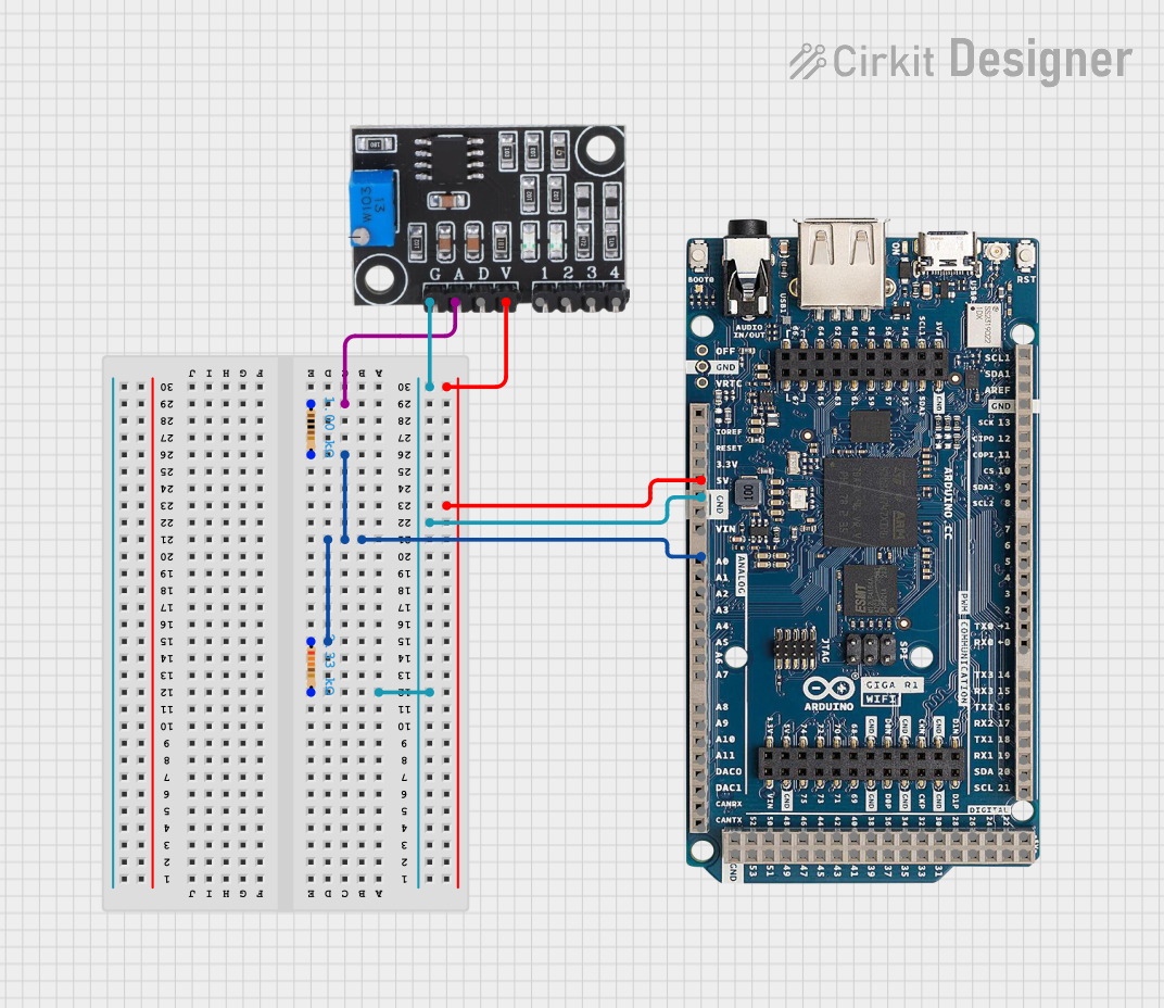
How to Use the Component in a Circuit

  1. Connect the VCC pin to a 3.3V or 5V power supply.
  2. Connect the GND pin to the ground of the power supply.
  3. Connect the Analog Output pin to an analog input on your microcontroller, such as an Arduino UNO.

Important Considerations and Best Practices

  • Ensure that the sensor is properly calibrated before use.
  • Avoid exposing the sensor to direct sunlight or high-intensity light sources.
  • Keep the sensor clean and free from obstructions that could affect readings.
  • Use a stable power supply to prevent fluctuations in the sensor output.

Example Code for Arduino UNO

// Grove Turbidity Sensor Example Code for Arduino UNO
const int turbidityPin = A0; // Analog input pin that the sensor is attached to

void setup() {
  Serial.begin(9600); // Initialize serial communication at 9600 bits per second
}

void loop() {
  int sensorValue = analogRead(turbidityPin); // Read the value from the sensor
  float voltage = sensorValue * (5.0 / 1023.0); // Convert the analog reading to voltage
  Serial.print("Turbidity Voltage: ");
  Serial.print(voltage); // Print the voltage
  Serial.println(" V");
  delay(1000); // Wait for one second before reading again
}

Troubleshooting and FAQs

Common Issues Users Might Face

  • Inaccurate Readings: Ensure the sensor is calibrated correctly and that there are no air bubbles or debris on the sensor surface.
  • No Output Signal: Check all connections and ensure that the power supply is within the specified range.
  • Fluctuating Readings: Stabilize the power supply and avoid external light interference.

Solutions and Tips for Troubleshooting

  • Calibration: Perform calibration with a known turbidity standard to ensure accuracy.
  • Cleaning: Gently clean the sensor with distilled water and avoid touching the optical components.
  • Shielding: Use opaque tubing or a shield to protect the sensor from external light.

FAQs

Q: Can the sensor be used in saltwater? A: Yes, but ensure that the sensor is rinsed with fresh water after use to prevent corrosion.

Q: What is the lifespan of the sensor? A: With proper maintenance and use within its specifications, the sensor can last for several years.

Q: How often should the sensor be calibrated? A: Calibration frequency depends on usage, but it is recommended to calibrate the sensor before any critical measurements or after any significant changes in the measurement environment.

Note: This documentation is for the Grove Turbidity Sensor with the manufacturer part ID "Grove Trubilty sensor." Always refer to the manufacturer's official datasheet for the most accurate and detailed information.