How to Use INA333: Examples, Pinouts, and Specs
Introduction
The INA333 is a precision instrumentation amplifier designed for low-power applications. It features a low offset voltage, low noise, and a high common-mode rejection ratio (CMRR), making it ideal for amplifying small differential signals in noisy environments. The INA333 is widely used in medical instrumentation, sensor signal conditioning, and data acquisition systems due to its high accuracy and low power consumption.
Explore Projects Built with INA333
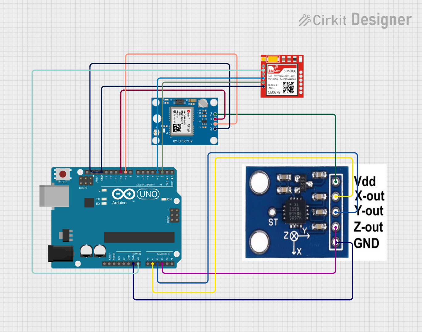

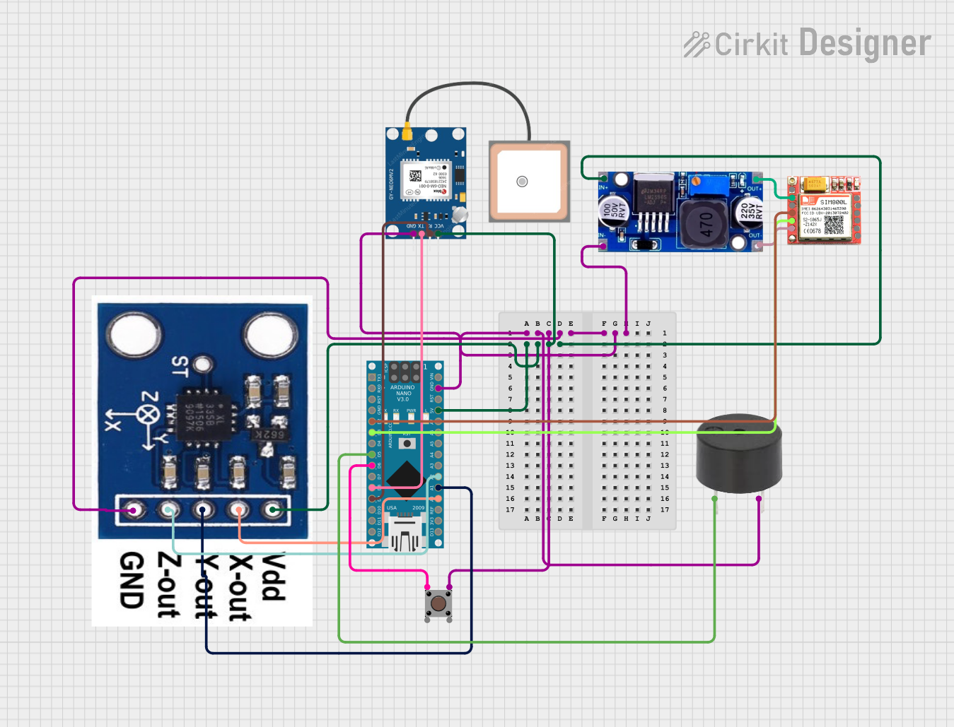
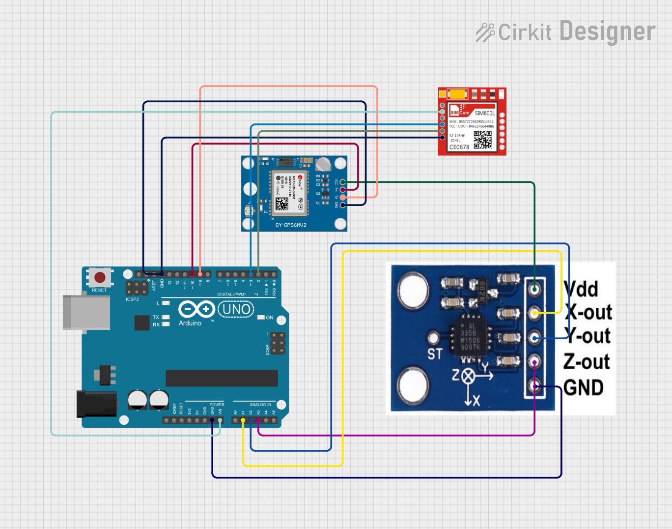
Explore Projects Built with INA333
Common Applications and Use Cases
- Medical instrumentation (e.g., ECG, EEG)
- Sensor signal amplification (e.g., strain gauges, thermocouples)
- Data acquisition systems
- Industrial process controls
- Portable and battery-powered devices
Technical Specifications
The INA333 offers excellent performance for precision applications. Below are its key technical specifications:
| Parameter | Value |
|---|---|
| Supply Voltage Range | 1.8 V to 5.5 V |
| Input Offset Voltage | ±25 µV (typical) |
| Input Bias Current | ±200 pA (typical) |
| Gain Range | 1 to 1000 (set by external resistor) |
| Common-Mode Rejection Ratio | 100 dB (minimum) |
| Bandwidth | 350 kHz (at G = 1) |
| Quiescent Current | 50 µA (typical) |
| Operating Temperature Range | -40°C to +125°C |
| Package Options | SOIC-8, VSSOP-8 |
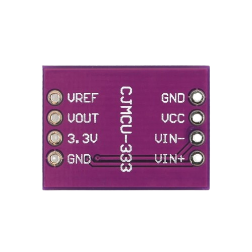
Pin Configuration and Descriptions
The INA333 is available in an 8-pin package. Below is the pinout and description:
| Pin Number | Pin Name | Description |
|---|---|---|
| 1 | RG | Gain-setting resistor connection |
| 2 | -IN | Inverting input |
| 3 | +IN | Non-inverting input |
| 4 | V- | Negative power supply (ground in single-supply) |
| 5 | REF | Reference voltage input (sets output baseline) |
| 6 | OUT | Output signal |
| 7 | V+ | Positive power supply |
| 8 | RG | Gain-setting resistor connection (same as Pin 1) |
Usage Instructions
The INA333 is straightforward to use in a circuit. Below are the steps and considerations for proper usage:
Basic Circuit Configuration
- Power Supply: Connect the V+ pin to a positive supply voltage (1.8 V to 5.5 V) and the V- pin to ground (for single-supply operation) or a negative voltage (for dual-supply operation).
- Input Connections: Connect the differential signal to the +IN and -IN pins. Ensure the input voltage is within the common-mode voltage range.
- Gain Setting: Use an external resistor (RG) between the RG pins (Pins 1 and 8) to set the gain. The gain is calculated as: [ G = 1 + \frac{50 , \text{k}\Omega}{R_G} ] For example, if ( R_G = 10 , \text{k}\Omega ), the gain will be ( G = 6 ).
- Reference Voltage: Connect the REF pin to a reference voltage to set the output baseline. For single-supply operation, connect REF to mid-supply (e.g., via a voltage divider).
- Output: The amplified signal will appear at the OUT pin.
Important Considerations
- Input Impedance: The INA333 has high input impedance, making it suitable for interfacing with high-impedance sensors.
- Decoupling Capacitors: Place a 0.1 µF ceramic capacitor close to the V+ pin to reduce power supply noise.
- Common-Mode Voltage: Ensure the input common-mode voltage is within the specified range to avoid distortion or clipping.
- Gain Resistor Tolerance: Use a precision resistor for RG to achieve accurate gain.
Example: Connecting to an Arduino UNO
The INA333 can be used to amplify small sensor signals for an Arduino UNO. Below is an example circuit and code for reading a differential signal:
Circuit
- Connect the INA333's +IN and -IN pins to the sensor's differential output.
- Set the gain using an appropriate RG resistor.
- Connect the OUT pin to an analog input pin on the Arduino (e.g., A0).
- Power the INA333 with the Arduino's 5V and GND pins.
Arduino Code
// INA333 Example Code for Arduino UNO
// Reads the amplified signal from the INA333 and prints it to the Serial Monitor

const int analogPin = A0; // Analog pin connected to INA333 OUT pin

void setup() {
  Serial.begin(9600); // Initialize serial communication at 9600 baud
}

void loop() {
  int sensorValue = analogRead(analogPin); // Read the analog value (0-1023)

  // Convert the analog value to voltage (assuming 5V reference)
  float voltage = sensorValue * (5.0 / 1023.0);

  // Print the voltage to the Serial Monitor
  Serial.print("Voltage: ");
  Serial.print(voltage, 3); // Print voltage with 3 decimal places
  Serial.println(" V");

  delay(500); // Wait for 500 ms before the next reading
}
Troubleshooting and FAQs
Common Issues and Solutions
No Output Signal:
- Verify the power supply connections (V+ and V-).
- Check that the REF pin is properly connected to a reference voltage.
- Ensure the input signal is within the common-mode voltage range.
Output Clipping:
- Check if the gain is set too high, causing the output to exceed the supply voltage range.
- Reduce the gain by increasing the RG resistor value.
High Noise in Output:
- Add decoupling capacitors near the power supply pins.
- Ensure proper grounding and minimize noise sources near the circuit.
Incorrect Gain:
- Verify the RG resistor value and its tolerance.
- Ensure the resistor is connected correctly between the RG pins.
FAQs
Q: Can the INA333 operate with a single power supply?
A: Yes, the INA333 can operate with a single supply voltage as low as 1.8 V. In this case, connect the V- pin to ground and set the REF pin to mid-supply.
Q: What is the maximum gain I can achieve with the INA333?
A: The maximum gain is 1000, which can be achieved by using an appropriate RG resistor. However, ensure the input and output signals remain within the specified voltage ranges.
Q: How do I minimize offset voltage errors?
A: Use precision resistors for the gain-setting resistor (RG) and ensure the REF pin is connected to a stable reference voltage.
Q: Can I use the INA333 for AC signals?
A: Yes, the INA333 can amplify AC signals. Use coupling capacitors at the input to block any DC offset if necessary.
By following these guidelines, the INA333 can be effectively used in a wide range of precision amplification applications.