How to Use Modul LM2596: Examples, Pinouts, and Specs
Introduction
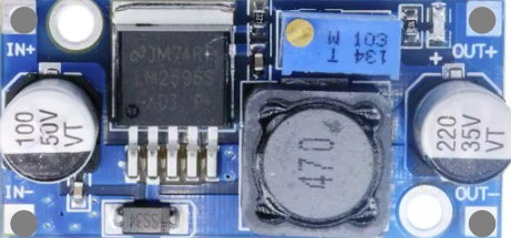
The LM2596 is a step-down (buck) voltage regulator module designed to efficiently convert a higher input voltage to a lower, stable output voltage. It is widely used in power supply applications due to its high efficiency, adjustable output voltage, and built-in overcurrent protection. This module is ideal for powering low-voltage devices from higher-voltage sources, such as batteries or unregulated power supplies.
Explore Projects Built with Modul LM2596


Explore Projects Built with Modul LM2596
Common Applications and Use Cases
- Powering microcontrollers, sensors, and other low-voltage devices
- Battery-powered systems requiring efficient voltage regulation
- DIY electronics projects and prototyping
- Replacing linear voltage regulators for improved efficiency
- LED drivers and portable device chargers
Technical Specifications
The LM2596 module is built around the LM2596 IC and includes additional components for ease of use. Below are its key technical specifications:
| Parameter | Value |
|---|---|
| Input Voltage Range | 4.5V to 40V |
| Output Voltage Range | 1.25V to 37V (adjustable via potentiometer) |
| Output Current | Up to 3A (with proper heat dissipation) |
| Efficiency | Up to 92% |
| Switching Frequency | 150 kHz |
| Output Ripple | ≤ 30 mV |
| Operating Temperature | -40°C to +85°C |
| Dimensions | ~45mm x 20mm x 14mm |
Pin Configuration and Descriptions
The LM2596 module typically has three main pins for input and output connections:
| Pin | Label | Description |
|---|---|---|
| 1 | VIN | Input voltage (4.5V to 40V) |
| 2 | GND | Ground (common for input and output) |
| 3 | VOUT | Regulated output voltage (1.25V to 37V) |
Usage Instructions
How to Use the LM2596 in a Circuit
Connect the Input Voltage (VIN):
- Attach the positive terminal of your power source to the
VINpin. - Connect the negative terminal of your power source to the
GNDpin.
- Attach the positive terminal of your power source to the
Adjust the Output Voltage:
- Use the onboard potentiometer to set the desired output voltage.
- Turn the potentiometer clockwise to increase the output voltage or counterclockwise to decrease it.
- Use a multimeter to measure the output voltage at the
VOUTpin while adjusting.
Connect the Load:
- Attach the positive terminal of your load to the
VOUTpin. - Connect the negative terminal of your load to the
GNDpin.
- Attach the positive terminal of your load to the
Verify Connections:
- Double-check all connections to ensure proper polarity and avoid short circuits.
Important Considerations and Best Practices
- Heat Dissipation: The LM2596 module can handle up to 3A of output current, but proper heat dissipation (e.g., a heatsink) is required for high-current applications.
- Input Voltage: Ensure the input voltage is at least 1.5V higher than the desired output voltage for stable operation.
- Output Ripple: Add a capacitor (e.g., 100µF) across the output terminals to reduce voltage ripple if needed.
- Polarity Protection: The module does not have built-in reverse polarity protection. Ensure correct polarity when connecting the power source.
Example: Using LM2596 with Arduino UNO
The LM2596 can be used to power an Arduino UNO from a higher voltage source, such as a 12V battery. Below is an example circuit and Arduino code:
Circuit Connections
- Connect the 12V battery's positive terminal to the
VINpin of the LM2596. - Connect the battery's negative terminal to the
GNDpin of the LM2596. - Adjust the LM2596 output to 5V using the potentiometer.
- Connect the
VOUTpin of the LM2596 to the Arduino UNO's5Vpin. - Connect the
GNDpin of the LM2596 to the Arduino UNO'sGNDpin.
Arduino Code Example
// Example code to blink an LED connected to pin 13 of Arduino UNO
// Ensure the Arduino is powered via the LM2596 module (set to 5V output)

void setup() {
  pinMode(13, OUTPUT); // Set pin 13 as an output pin
}

void loop() {
  digitalWrite(13, HIGH); // Turn the LED on
  delay(1000);            // Wait for 1 second
  digitalWrite(13, LOW);  // Turn the LED off
  delay(1000);            // Wait for 1 second
}
Troubleshooting and FAQs
Common Issues and Solutions
No Output Voltage:
- Cause: Incorrect input polarity or loose connections.
- Solution: Verify the input voltage polarity and ensure all connections are secure.
Output Voltage Not Adjustable:
- Cause: Faulty potentiometer or incorrect input voltage.
- Solution: Check the input voltage and replace the potentiometer if necessary.
Excessive Heat:
- Cause: High output current or insufficient heat dissipation.
- Solution: Add a heatsink to the LM2596 IC or reduce the load current.
High Output Ripple:
- Cause: Insufficient filtering or high-frequency noise.
- Solution: Add a capacitor (e.g., 100µF to 470µF) across the output terminals.
FAQs
Q: Can the LM2596 module be used with a 24V input?
A: Yes, the LM2596 supports input voltages up to 40V. Ensure the output voltage is set appropriately and does not exceed the input voltage.
Q: Is the LM2596 suitable for powering sensitive devices?
A: Yes, but for very sensitive devices, consider adding additional filtering capacitors to minimize output ripple.
Q: Can I use the LM2596 to step up voltage?
A: No, the LM2596 is a step-down (buck) regulator and cannot increase the input voltage.
Q: How do I calculate the efficiency of the LM2596?
A: Efficiency can be calculated using the formula:
[
\text{Efficiency} = \left( \frac{\text{Output Power}}{\text{Input Power}} \right) \times 100
]
Measure the input and output voltages and currents to determine power values.
By following this documentation, you can effectively use the LM2596 module in your projects and troubleshoot common issues.