How to Use Push Button Round: Examples, Pinouts, and Specs
Introduction
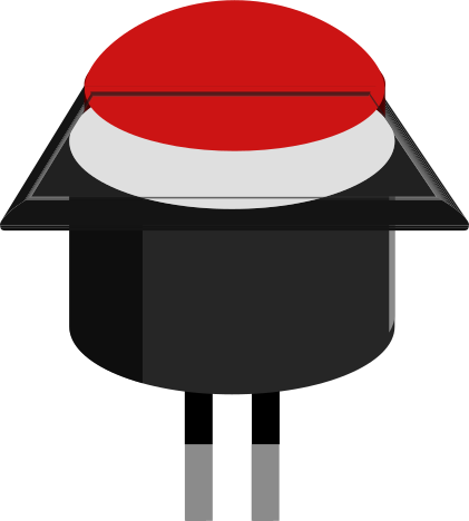
A round push button is a simple yet essential electronic component used to control the flow of electric current in a circuit. It acts as a mechanical switch that can be pressed to either make (close) or break (open) an electrical connection. This type of button is commonly used in various applications such as consumer electronics, industrial machinery, and hobbyist projects, including interfacing with microcontrollers like the Arduino UNO.
Explore Projects Built with Push Button Round
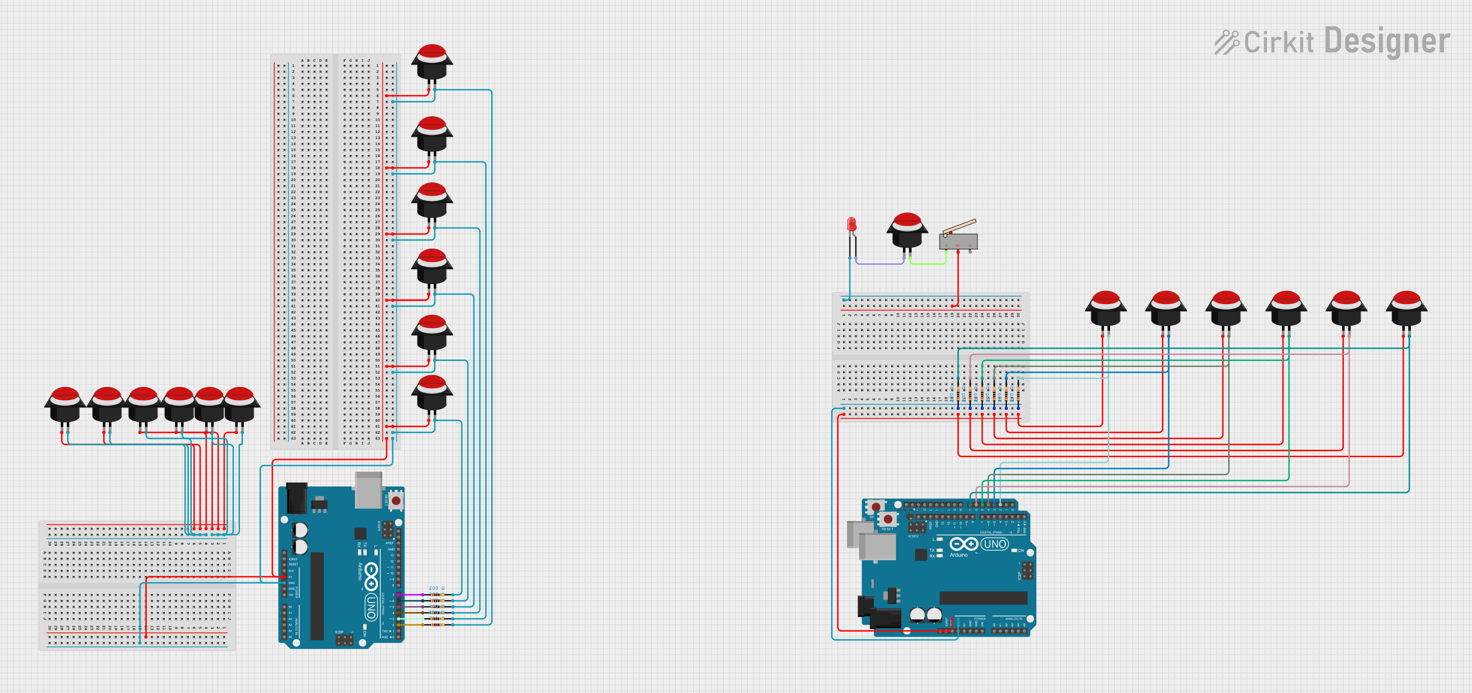

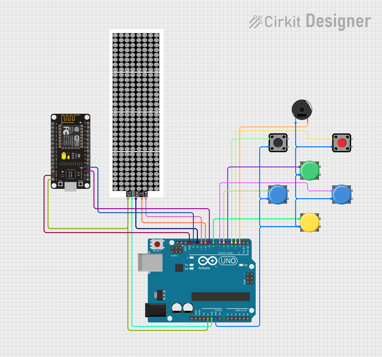

Explore Projects Built with Push Button Round
Common Applications and Use Cases
- Initiating an action when pressed (e.g., starting a machine, lighting an LED)
- User input for interactive projects
- Debounce circuits to ensure single action per press
- As a reset button in electronic devices
Technical Specifications
Key Technical Details
- Voltage Rating: Typically 3.3V to 5V for logic level circuits
- Current Rating: Varies, often around 10mA to 50mA for signal-level circuits
- Contact Type: Momentary normally open (NO) or normally closed (NC)
- Durability: Rated for a certain number of cycles (e.g., 100,000 presses)
Pin Configuration and Descriptions
| Pin Number | Description |
|---|---|
| 1 | Common (COM) |
| 2 | Normally Open (NO) |
| 3 | Normally Closed (NC) |
Note: Some round push buttons may only have two pins (COM and NO) if they do not offer a normally closed configuration.
Usage Instructions
How to Use the Component in a Circuit
- Identify the pinout of the push button.
- Connect the common pin (COM) to one side of the circuit you wish to control.
- Connect the normally open pin (NO) to the other side of the circuit.
- When the button is pressed, the circuit between COM and NO will close, allowing current to flow.
Important Considerations and Best Practices
- Use a pull-up or pull-down resistor to ensure a stable state when the button is not pressed.
- Consider debouncing the button either through hardware (e.g., RC filter) or software to prevent multiple triggers from mechanical vibrations.
- Ensure the button's voltage and current ratings are not exceeded to avoid damage.
Example Code for Arduino UNO
// Define the pin connected to the push button
const int buttonPin = 2;
// Define the pin connected to an LED (or other device)
const int ledPin = 13;

// Variable to store the state of the button
int buttonState = 0;

void setup() {
  // Initialize the LED pin as an output
  pinMode(ledPin, OUTPUT);
  // Initialize the push button pin as an input
  pinMode(buttonPin, INPUT_PULLUP);
}

void loop() {
  // Read the state of the push button value
  buttonState = digitalRead(buttonPin);

  // Check if the push button is pressed
  // If it is, the buttonState is LOW
  if (buttonState == LOW) {
    // Turn on the LED
    digitalWrite(ledPin, HIGH);
  } else {
    // Turn off the LED
    digitalWrite(ledPin, LOW);
  }
}
Note: The INPUT_PULLUP mode enables the internal pull-up resistor, which is a best practice for push button circuits.
Troubleshooting and FAQs
Common Issues Users Might Face
- Button does not respond: Ensure the button is correctly wired and the pull-up/pull-down resistor is in place.
- Multiple triggers from a single press: This is likely due to button bounce. Implement a debounce mechanism in hardware or software.
- Button stuck in pressed state: Check for any physical obstructions or damage to the button mechanism.
Solutions and Tips for Troubleshooting
- Verify the connections and ensure there are no loose wires.
- Test the button with a multimeter to ensure it is functioning correctly.
- Replace the button if it has surpassed its rated number of cycles or appears damaged.
FAQs
Q: Can I use a round push button with a higher voltage rating in a low-voltage circuit?
A: Yes, using a button with a higher voltage rating than your circuit's voltage is generally safe.
Q: How do I know if my button requires debouncing?
A: If you notice erratic behavior or multiple activations with a single press, debouncing is likely necessary.
Q: What is the difference between normally open and normally closed buttons?
A: Normally open buttons make the circuit when pressed, while normally closed buttons break the circuit when pressed.