How to Use USB to RS485 FT232RL: Examples, Pinouts, and Specs
Introduction
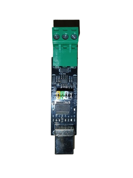
The USB to RS485 FT232RL is a versatile converter module that bridges USB devices and RS485 networks. It is built around the FT232RL chip, which provides reliable and high-speed serial communication. Supporting data rates of up to 3 Mbps, this module is widely used in industrial automation, control systems, and other applications requiring robust and long-distance serial communication.
Explore Projects Built with USB to RS485 FT232RL


Explore Projects Built with USB to RS485 FT232RL
Common Applications
- Industrial automation and control systems
- Building management systems (BMS)
- Serial communication with PLCs, sensors, and actuators
- Data acquisition systems
- Home automation and IoT devices
Technical Specifications
Below are the key technical details of the USB to RS485 FT232RL module:
| Parameter | Specification |
|---|---|
| Chipset | FT232RL |
| Communication Protocol | RS485 |
| USB Interface | USB 2.0 (compatible with USB 1.1/3.0) |
| Data Rate | Up to 3 Mbps |
| Operating Voltage | 5V (via USB) |
| RS485 Signal Voltage | -7V to +12V |
| Operating Temperature | -40°C to +85°C |
| Dimensions | Varies by module (typically compact) |
Pin Configuration and Descriptions
The USB to RS485 FT232RL module typically has the following pinouts:
| Pin Name | Description |
|---|---|
| GND | Ground connection |
| A (D+) | RS485 differential signal (non-inverting) |
| B (D-) | RS485 differential signal (inverting) |
| 5V | Power supply (provided via USB) |
| TXD | Transmit data (handled internally by the FT232RL chip) |
| RXD | Receive data (handled internally by the FT232RL chip) |
| DE/RE | Driver Enable/Receiver Enable (automatically managed by the FT232RL chip) |
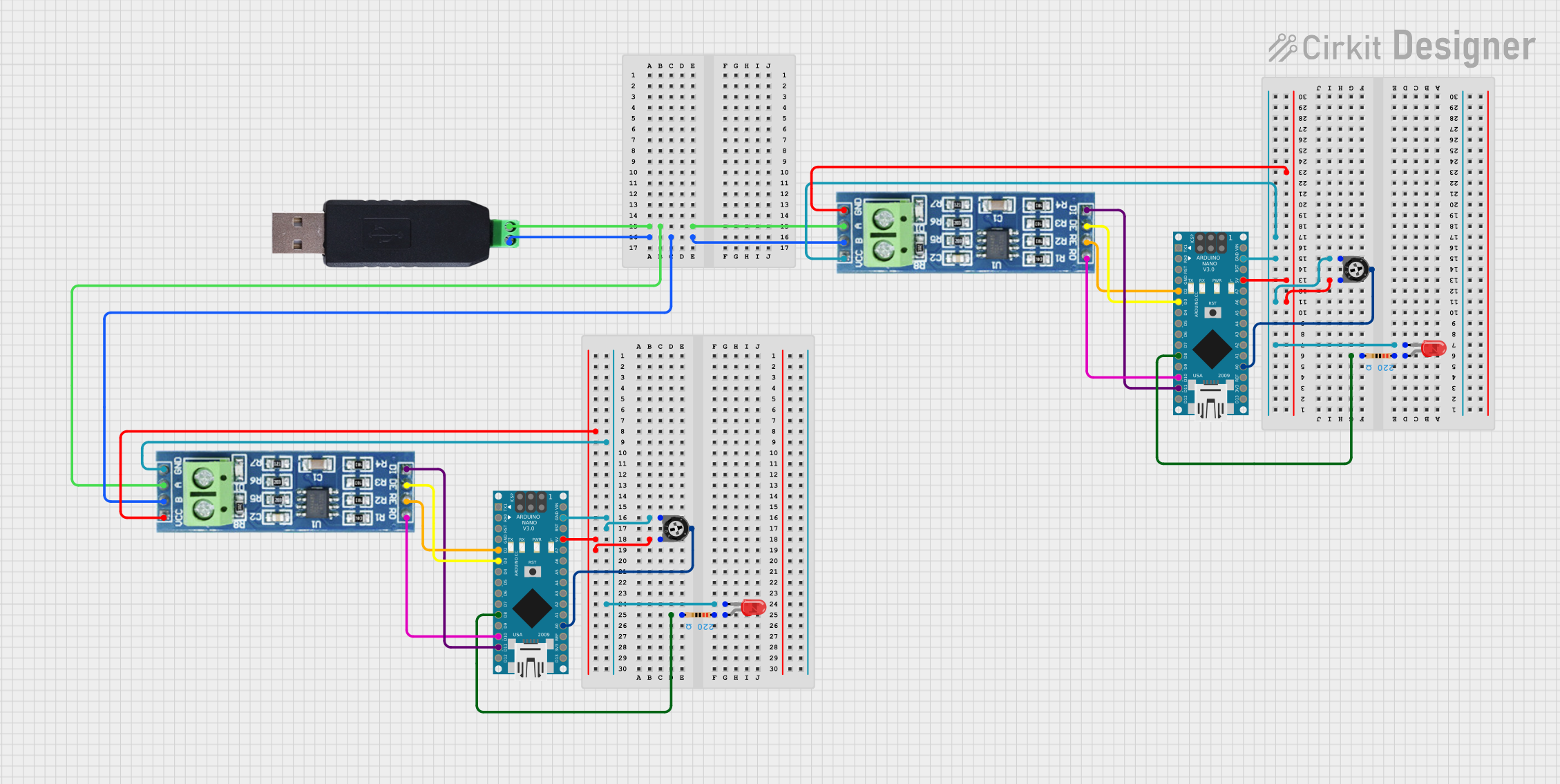
Usage Instructions
How to Use the USB to RS485 FT232RL in a Circuit
- Connect the USB Interface: Plug the module into a USB port on your computer or host device. Ensure the necessary FTDI drivers are installed (available from FTDI's official website).
- Connect RS485 Devices:
- Connect the
A (D+)pin of the module to theAterminal of the RS485 device. - Connect the
B (D-)pin of the module to theBterminal of the RS485 device. - Connect the
GNDpin of the module to the ground of the RS485 network.
- Connect the
- Power Supply: The module is powered directly via the USB connection, so no external power supply is required.
- Driver Installation: Install the FT232RL drivers on your computer. These drivers create a virtual COM port for communication.
- Communication: Use a terminal program (e.g., PuTTY, RealTerm) or custom software to send and receive data over the RS485 network.
Important Considerations
- Termination Resistor: For long-distance communication, ensure a 120-ohm termination resistor is placed across the
AandBlines at both ends of the RS485 network. - Grounding: Proper grounding is essential to avoid communication errors or damage to the module.
- Baud Rate: Configure the baud rate in your software to match the RS485 device's settings.
- Automatic Flow Control: The FT232RL chip automatically manages the DE/RE signals, simplifying RS485 communication.
Example: Connecting to an Arduino UNO
The USB to RS485 FT232RL can be used to communicate between an Arduino UNO and an RS485 device. Below is an example Arduino sketch:
#include <SoftwareSerial.h>

// Define RX and TX pins for SoftwareSerial
SoftwareSerial RS485Serial(10, 11); // RX = pin 10, TX = pin 11

void setup() {
  Serial.begin(9600); // Initialize USB serial communication
  RS485Serial.begin(9600); // Initialize RS485 communication

  Serial.println("RS485 Communication Initialized");
}

void loop() {
  // Send data to RS485 device
  RS485Serial.println("Hello RS485 Device!");

  // Check if data is available from RS485 device
  if (RS485Serial.available()) {
    String receivedData = RS485Serial.readString();
    Serial.print("Received: ");
    Serial.println(receivedData);
  }

  delay(1000); // Wait 1 second before sending the next message
}
Notes:
- Replace
10and11with the actual pins used for RX and TX on your Arduino. - Ensure the baud rate (
9600in this example) matches the RS485 device's settings.
Troubleshooting and FAQs
Common Issues and Solutions
No Communication with RS485 Device:
- Verify the
AandBconnections. Swapping these lines may resolve the issue. - Check if the RS485 device is powered and properly configured.
- Verify the
Driver Not Recognized:
- Ensure the FT232RL drivers are installed. Download the latest drivers from FTDI's official website.
- Try a different USB cable or port.
Data Corruption or Noise:
- Use a 120-ohm termination resistor across the
AandBlines. - Ensure proper grounding of all devices in the RS485 network.
- Use a 120-ohm termination resistor across the
Module Overheating:
- Check for short circuits or excessive current draw on the RS485 network.
FAQs
Q: Can I use this module with a Raspberry Pi?
A: Yes, the USB to RS485 FT232RL module is compatible with Raspberry Pi. Simply connect it to a USB port and install the FTDI drivers.
Q: What is the maximum cable length for RS485 communication?
A: RS485 supports cable lengths of up to 1200 meters (4000 feet) at lower baud rates. For higher baud rates, shorter cable lengths are recommended.
Q: Does the module support half-duplex communication?
A: Yes, RS485 is inherently a half-duplex protocol, and the FT232RL chip manages the DE/RE signals automatically.
Q: Can I connect multiple devices to the RS485 network?
A: Yes, RS485 supports multi-drop communication with up to 32 devices on the same network.
By following this documentation, you can effectively use the USB to RS485 FT232RL module in your projects.