How to Use Power LED 5V 2W 0.8-0.9A: Examples, Pinouts, and Specs
Introduction
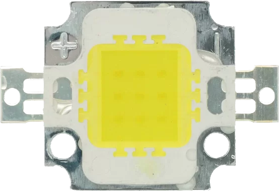
The Power LED 5V 2W 0.8-0.9A (Manufacturer: mio, Part ID: led 5v) is a high-efficiency light-emitting diode (LED) designed for reliable and bright illumination. Operating at 5 volts with a power rating of 2 watts, this LED is capable of delivering consistent performance while drawing a current of 0.8 to 0.9 amps. Its compact design and high brightness make it ideal for a variety of applications, including:
- General-purpose lighting
- Indicator lights
- DIY electronics projects
- Backlighting for displays
- Automotive and decorative lighting
This LED is a versatile component suitable for both hobbyists and professionals seeking efficient and durable lighting solutions.
Explore Projects Built with Power LED 5V 2W 0.8-0.9A


Explore Projects Built with Power LED 5V 2W 0.8-0.9A
Technical Specifications
Below are the key technical details for the Power LED 5V 2W 0.8-0.9A:
| Parameter | Value |
|---|---|
| Manufacturer | mio |
| Part ID | led 5v |
| Operating Voltage | 5V DC |
| Power Rating | 2W |
| Current Draw | 0.8-0.9A |
| Luminous Intensity | ~200-300 lumens (typical) |
| Color Temperature | Varies (e.g., warm white, cool white, or RGB) |
| Viewing Angle | ~120° |
| Operating Temperature | -20°C to +70°C |
| Dimensions | ~10mm x 10mm (varies by model) |
| Mounting Type | Through-hole or surface-mount |
Pin Configuration
The Power LED 5V 2W 0.8-0.9A typically has two pins for electrical connections:
| Pin | Name | Description |
|---|---|---|
| 1 | Anode (+) | Positive terminal; connect to 5V supply |
| 2 | Cathode (-) | Negative terminal; connect to ground |
Note: Ensure correct polarity when connecting the LED to avoid damage.
Usage Instructions
How to Use the Component in a Circuit
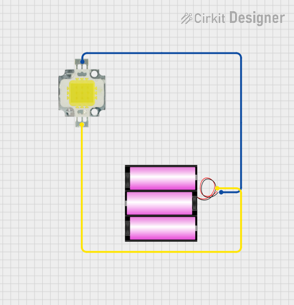
- Power Supply: Connect the LED to a stable 5V DC power source. Ensure the power supply can provide at least 0.9A to avoid underpowering the LED.
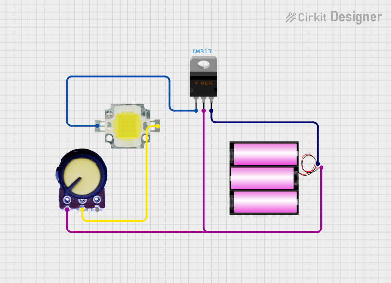
- Current Limiting: While the LED is designed to operate at 5V without an external resistor, ensure the power source is regulated to prevent voltage spikes.
- Polarity: Connect the Anode (+) to the positive terminal of the power supply and the Cathode (-) to the ground. Reversing the polarity may damage the LED.
- Heat Management: As the LED operates at 2W, it may generate heat. Use a heatsink or ensure proper ventilation to maintain optimal performance and longevity.
- Optional Control: For dimming or brightness control, you can use a PWM (Pulse Width Modulation) signal from a microcontroller like an Arduino.
Example Circuit with Arduino UNO
The following example demonstrates how to control the brightness of the LED using an Arduino UNO and PWM:
// Example: Controlling the brightness of a Power LED 5V 2W using Arduino UNO
// Connect the LED's Anode (+) to pin 9 (via a transistor if needed) and Cathode (-) to GND.

const int ledPin = 9; // PWM pin connected to the LED

void setup() {
  pinMode(ledPin, OUTPUT); // Set pin 9 as an output
}

void loop() {
  // Gradually increase brightness
  for (int brightness = 0; brightness <= 255; brightness++) {
    analogWrite(ledPin, brightness); // Set PWM duty cycle
    delay(10); // Small delay for smooth transition
  }

  // Gradually decrease brightness
  for (int brightness = 255; brightness >= 0; brightness--) {
    analogWrite(ledPin, brightness); // Set PWM duty cycle
    delay(10); // Small delay for smooth transition
  }
}
Important Notes:
- If the LED draws more current than the Arduino pin can handle, use a transistor (e.g., NPN type) to drive the LED.
- Always verify the current and voltage ratings of your components to avoid damage.
Best Practices
- Use a regulated 5V power supply to ensure stable operation.
- Avoid exceeding the maximum current rating (0.9A) to prevent overheating or damage.
- If using multiple LEDs, connect them in parallel with individual current-limiting resistors or drivers.
Troubleshooting and FAQs
Common Issues and Solutions
| Issue | Possible Cause | Solution |
|---|---|---|
| LED does not light up | Incorrect polarity | Verify Anode (+) and Cathode (-) connections. |
| LED flickers or dims unexpectedly | Insufficient power supply | Use a power supply capable of providing at least 0.9A. |
| LED overheats | Poor heat dissipation | Add a heatsink or improve ventilation. |
| LED burns out | Voltage or current exceeds specifications | Use a regulated 5V supply and ensure current is within range. |
FAQs
Can I use this LED with a 3.3V power supply?
- No, the LED is designed to operate at 5V. Using a lower voltage may result in insufficient brightness or failure to light up.
Do I need a resistor for this LED?
- No external resistor is required if the power supply is regulated at 5V. However, ensure the supply is stable to avoid voltage spikes.
Can I connect multiple LEDs in series?
- No, this LED is designed for 5V operation. Connecting multiple LEDs in series would require a higher voltage.
What is the expected lifespan of this LED?
- With proper usage and heat management, the LED can last up to 50,000 hours.
By following the guidelines and best practices outlined in this documentation, you can ensure optimal performance and longevity of the Power LED 5V 2W 0.8-0.9A in your projects.