Cirkit Designer Logo
Cirkit Designer
Your all-in-one circuit design IDE
Home / 
Component Documentation

How to Use SBT5333 Step Down: Examples, Pinouts, and Specs

Image of SBT5333 Step Down
Cirkit Designer LogoDesign with SBT5333 Step Down in Cirkit Designer

Introduction

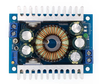
The SBT5333 Step Down Converter, manufactured by Step Down, is a high-efficiency DC-DC buck converter designed to reduce voltage from a higher level to a lower level. This component is ideal for applications requiring stable and efficient voltage regulation, such as powering microcontrollers, sensors, and other electronic devices from a higher voltage source.

Explore Projects Built with SBT5333 Step Down

Use Cirkit Designer to design, explore, and prototype these projects online. Some projects support real-time simulation. Click "Open Project" to start designing instantly!
Battery-Powered UPS with Step-Down Buck Converter and BMS
Image of Mini ups: A project utilizing SBT5333 Step Down in a practical application
This circuit is a power management system that steps down a 240V AC input to a lower DC voltage using a buck converter, which then powers a 40W UPS. The UPS is controlled by a rocker switch and is backed up by a battery management system (BMS) connected to three 3.7V batteries in series, ensuring continuous power supply.
Cirkit Designer LogoOpen Project in Cirkit Designer
Battery-Powered Adjustable Voltage Regulator with Li-ion 18650 Batteries and BMS
Image of mini ups: A project utilizing SBT5333 Step Down in a practical application
This circuit is a power management system that uses four Li-ion 18650 batteries connected to a 2S 30A BMS for battery management and protection. The system includes step-up and step-down voltage regulators to provide adjustable output voltages, controlled by a rocker switch, and multiple DC jacks for power input and output.
Cirkit Designer LogoOpen Project in Cirkit Designer
Battery-Powered 18650 Li-ion Charger with USB Output and Adjustable Voltage Regulator
Image of Breadboard: A project utilizing SBT5333 Step Down in a practical application
This circuit is a battery management and power supply system that uses three 3.7V batteries connected to a 3S 10A Li-ion 18650 Charger Protection Board Module for balanced charging and protection. The system includes a TP4056 Battery Charging Protection Module for additional charging safety, a Step Up Boost Power Converter to regulate and boost the voltage, and a USB regulator to provide a stable 5V output, controlled by a push switch.
Cirkit Designer LogoOpen Project in Cirkit Designer
Arduino Nano-Based Stepper Motor Controller with SD Card Logging
Image of RPM: A project utilizing SBT5333 Step Down in a practical application
This circuit features an Arduino Nano microcontroller interfaced with an SD card module for data storage and a DRV8825 driver to control a bipolar stepper motor. The system is powered by a 12V power supply, which is stepped down to 5V for the Arduino and SD module using a step-down converter.
Cirkit Designer LogoOpen Project in Cirkit Designer

Explore Projects Built with SBT5333 Step Down

Use Cirkit Designer to design, explore, and prototype these projects online. Some projects support real-time simulation. Click "Open Project" to start designing instantly!
Image of Mini ups: A project utilizing SBT5333 Step Down in a practical application
Battery-Powered UPS with Step-Down Buck Converter and BMS
This circuit is a power management system that steps down a 240V AC input to a lower DC voltage using a buck converter, which then powers a 40W UPS. The UPS is controlled by a rocker switch and is backed up by a battery management system (BMS) connected to three 3.7V batteries in series, ensuring continuous power supply.
Cirkit Designer LogoOpen Project in Cirkit Designer
Image of mini ups: A project utilizing SBT5333 Step Down in a practical application
Battery-Powered Adjustable Voltage Regulator with Li-ion 18650 Batteries and BMS
This circuit is a power management system that uses four Li-ion 18650 batteries connected to a 2S 30A BMS for battery management and protection. The system includes step-up and step-down voltage regulators to provide adjustable output voltages, controlled by a rocker switch, and multiple DC jacks for power input and output.
Cirkit Designer LogoOpen Project in Cirkit Designer
Image of Breadboard: A project utilizing SBT5333 Step Down in a practical application
Battery-Powered 18650 Li-ion Charger with USB Output and Adjustable Voltage Regulator
This circuit is a battery management and power supply system that uses three 3.7V batteries connected to a 3S 10A Li-ion 18650 Charger Protection Board Module for balanced charging and protection. The system includes a TP4056 Battery Charging Protection Module for additional charging safety, a Step Up Boost Power Converter to regulate and boost the voltage, and a USB regulator to provide a stable 5V output, controlled by a push switch.
Cirkit Designer LogoOpen Project in Cirkit Designer
Image of RPM: A project utilizing SBT5333 Step Down in a practical application
Arduino Nano-Based Stepper Motor Controller with SD Card Logging
This circuit features an Arduino Nano microcontroller interfaced with an SD card module for data storage and a DRV8825 driver to control a bipolar stepper motor. The system is powered by a 12V power supply, which is stepped down to 5V for the Arduino and SD module using a step-down converter.
Cirkit Designer LogoOpen Project in Cirkit Designer

Common Applications and Use Cases

  • Powering microcontrollers (e.g., Arduino, Raspberry Pi)
  • Battery-powered projects
  • Robotics and automation systems
  • LED lighting systems
  • Portable electronic devices

Technical Specifications

Key Technical Details

Parameter Value
Manufacturer Step Down
Part ID DC-DC 200W 12A DC 5-40V
Input Voltage Range 5V to 40V
Output Voltage Range 1.2V to 35V
Maximum Output Current 12A
Maximum Output Power 200W
Efficiency Up to 95%
Switching Frequency 150kHz
Operating Temperature -40°C to +85°C

Pin Configuration and Descriptions

Pin Number Pin Name Description
1 VIN Input Voltage (5V to 40V)
2 GND Ground
3 VOUT Output Voltage (1.2V to 35V)
4 ADJ Output Voltage Adjustment

Usage Instructions

How to Use the Component in a Circuit

  1. Connect the Input Voltage (VIN): Connect the positive terminal of your power source (5V to 40V) to the VIN pin of the SBT5333.
  2. Connect the Ground (GND): Connect the ground terminal of your power source to the GND pin of the SBT5333.
  3. Connect the Output Voltage (VOUT): Connect the VOUT pin to the load that requires the regulated voltage.
  4. Adjust the Output Voltage (ADJ): Use a potentiometer or a fixed resistor to adjust the output voltage to the desired level.

Important Considerations and Best Practices

  • Heat Dissipation: Ensure proper heat dissipation by using a heatsink or adequate ventilation, especially when operating at high currents.
  • Input Voltage: Always ensure that the input voltage is within the specified range (5V to 40V) to avoid damaging the converter.
  • Output Voltage Adjustment: Use precise resistors or a high-quality potentiometer for accurate voltage adjustment.
  • Capacitors: Use appropriate input and output capacitors to stabilize the voltage and reduce noise.

Example Circuit with Arduino UNO

/*
  Example code to demonstrate the use of SBT5333 Step Down Converter
  with an Arduino UNO. This code reads the output voltage and displays
  it on the serial monitor.
*/

const int voltagePin = A0; // Analog pin to read the output voltage

void setup() {
  Serial.begin(9600); // Initialize serial communication at 9600 baud rate
}

void loop() {
  int sensorValue = analogRead(voltagePin); // Read the analog input
  float voltage = sensorValue * (5.0 / 1023.0); // Convert the analog reading to voltage
  Serial.print("Output Voltage: ");
  Serial.print(voltage);
  Serial.println(" V");
  delay(1000); // Wait for 1 second before the next reading
}

Troubleshooting and FAQs

Common Issues Users Might Face

  1. No Output Voltage:

    • Solution: Check the input voltage and ensure it is within the specified range. Verify all connections and ensure the ground is properly connected.
  2. Overheating:

    • Solution: Ensure proper heat dissipation by using a heatsink or providing adequate ventilation. Reduce the load current if necessary.
  3. Unstable Output Voltage:

    • Solution: Use appropriate input and output capacitors to stabilize the voltage. Check for loose connections and ensure the adjustment resistor/potentiometer is functioning correctly.

FAQs

  1. What is the maximum input voltage for the SBT5333?

    • The maximum input voltage is 40V.
  2. Can I use the SBT5333 to power my Arduino UNO?

    • Yes, you can use the SBT5333 to step down a higher voltage to 5V to power your Arduino UNO.
  3. How do I adjust the output voltage?

    • Use a potentiometer or a fixed resistor connected to the ADJ pin to adjust the output voltage to the desired level.
  4. What is the efficiency of the SBT5333?

    • The efficiency of the SBT5333 can be up to 95%, depending on the input and output voltage and the load current.

By following this documentation, users can effectively utilize the SBT5333 Step Down Converter in their electronic projects, ensuring efficient and stable voltage regulation.