Cirkit Designer Logo
Cirkit Designer
Your all-in-one circuit design IDE
Home / 
Component Documentation

How to Use plug: Examples, Pinouts, and Specs

Image of plug
Cirkit Designer LogoDesign with plug in Cirkit Designer

Introduction

A plug is an essential electronic component that serves as the interface between an electrical device and the power source. It is designed to connect safely and securely to a corresponding receptacle, allowing for the transfer of electrical power. Plugs are ubiquitous in electronic systems and are used in a variety of applications ranging from household appliances to industrial machinery.

Explore Projects Built with plug

Use Cirkit Designer to design, explore, and prototype these projects online. Some projects support real-time simulation. Click "Open Project" to start designing instantly!
Dual 5V Power Supply Distribution Circuit with Toggle Switch Control
Image of rfdriver: A project utilizing plug in a practical application
This circuit consists of two 5V 5A power supplies connected to an AC wall plug point, providing DC output through a 12-way connector. The ground connections from both power supplies are interconnected and also connected to the ground pins of two toggle switches. The DC outputs from the power supplies are separately connected to different pins on the 12-way connector, with each power supply output being switchable via one of the toggle switches.
Cirkit Designer LogoOpen Project in Cirkit Designer
Pushbutton Interface with General Purpose I/O Plug
Image of Assista GP IO: A project utilizing plug in a practical application
This circuit consists of a General Purpose Input/Output (GPIO) plug connected to four pushbuttons. Each pushbutton is wired to a unique input pin on the GPIO plug, allowing the state of each button (pressed or not pressed) to be detected individually. The common terminals of the pushbuttons are interconnected and likely serve as a ground or reference voltage connection.
Cirkit Designer LogoOpen Project in Cirkit Designer
Heater Control Circuit with Power Socket Integration
Image of Simple Water Heater: A project utilizing plug in a practical application
The circuit connects a heater to a power source via a socket. The heater is likely to be powered directly from the socket, with the positive and negative terminals of the socket providing the necessary voltage and ground connections to the heater. There are no control elements or sensors present in the circuit, indicating that the heater operates at a constant power level when connected.
Cirkit Designer LogoOpen Project in Cirkit Designer
Pushbutton-Controlled Interface with 40-Pin Connector and UBS Power Supply
Image of connect 4: A project utilizing plug in a practical application
This circuit consists of a 40-pin connector interfacing with four pushbuttons and a UBS power supply. The pushbuttons are used as inputs to the connector, which then relays the signals to other components or systems. The UBS power supply provides the necessary 24V power to the pushbuttons and the common ground for the circuit.
Cirkit Designer LogoOpen Project in Cirkit Designer

Explore Projects Built with plug

Use Cirkit Designer to design, explore, and prototype these projects online. Some projects support real-time simulation. Click "Open Project" to start designing instantly!
Image of rfdriver: A project utilizing plug in a practical application
Dual 5V Power Supply Distribution Circuit with Toggle Switch Control
This circuit consists of two 5V 5A power supplies connected to an AC wall plug point, providing DC output through a 12-way connector. The ground connections from both power supplies are interconnected and also connected to the ground pins of two toggle switches. The DC outputs from the power supplies are separately connected to different pins on the 12-way connector, with each power supply output being switchable via one of the toggle switches.
Cirkit Designer LogoOpen Project in Cirkit Designer
Image of Assista GP IO: A project utilizing plug in a practical application
Pushbutton Interface with General Purpose I/O Plug
This circuit consists of a General Purpose Input/Output (GPIO) plug connected to four pushbuttons. Each pushbutton is wired to a unique input pin on the GPIO plug, allowing the state of each button (pressed or not pressed) to be detected individually. The common terminals of the pushbuttons are interconnected and likely serve as a ground or reference voltage connection.
Cirkit Designer LogoOpen Project in Cirkit Designer
Image of Simple Water Heater: A project utilizing plug in a practical application
Heater Control Circuit with Power Socket Integration
The circuit connects a heater to a power source via a socket. The heater is likely to be powered directly from the socket, with the positive and negative terminals of the socket providing the necessary voltage and ground connections to the heater. There are no control elements or sensors present in the circuit, indicating that the heater operates at a constant power level when connected.
Cirkit Designer LogoOpen Project in Cirkit Designer
Image of connect 4: A project utilizing plug in a practical application
Pushbutton-Controlled Interface with 40-Pin Connector and UBS Power Supply
This circuit consists of a 40-pin connector interfacing with four pushbuttons and a UBS power supply. The pushbuttons are used as inputs to the connector, which then relays the signals to other components or systems. The UBS power supply provides the necessary 24V power to the pushbuttons and the common ground for the circuit.
Cirkit Designer LogoOpen Project in Cirkit Designer

Common Applications and Use Cases

  • Powering household appliances like TVs, refrigerators, and lamps.
  • Providing power to office equipment such as computers, printers, and photocopiers.
  • Connecting power tools and machinery in industrial settings.
  • Charging portable devices when used with adapters.

Technical Specifications

Key Technical Details

Specification Description
Voltage Rating The maximum voltage the plug can handle, typically 110-240V AC.
Current Rating The maximum current the plug can carry, often between 2.5A to 20A.
Power Rating The maximum power the plug can transmit, calculated as Voltage x Current.
Number of Pins The number of conductive pins or prongs, usually 2 or 3.
Pin Material The conductive material used for pins, commonly brass or copper.
Insulation Material The material used to insulate the plug, such as PVC or rubber.
Safety Standards Compliance with international standards like IEC, UL, or CE.

Pin Configuration and Descriptions

Pin Number Description
1 Live (L) - Carries the current to the device.
2 Neutral (N) - Completes the circuit by carrying current back.
3 Earth (E) - Safety ground to prevent electric shock (if applicable).

Usage Instructions

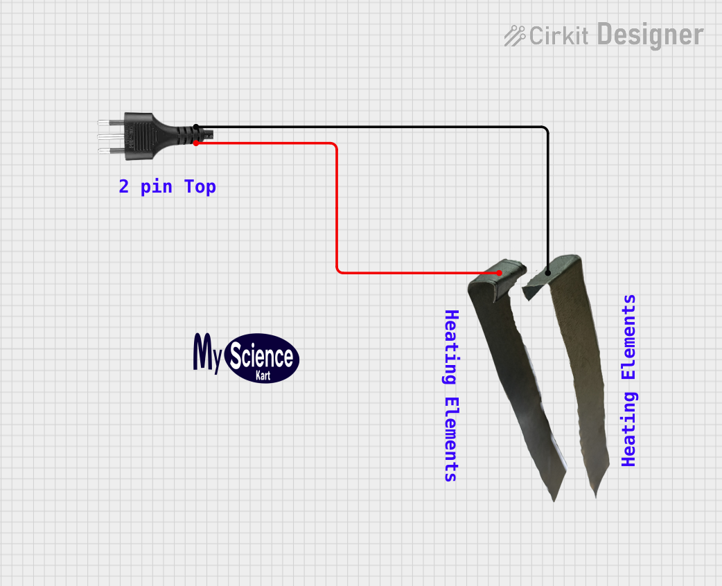
How to Use the Plug in a Circuit

  1. Inspect the Plug: Before use, inspect the plug for any damage or wear.
  2. Check Ratings: Ensure the plug's voltage and current ratings match the device and power source.
  3. Wiring: Connect the wires from the device to the correct pins of the plug. Typically, live (L) is brown, neutral (N) is blue, and earth (E) is green-yellow.
  4. Secure Connections: Tighten any screws or clamps to secure the wires in place.
  5. Insulation: Ensure that the wiring is properly insulated to prevent short circuits.
  6. Insertion: Gently insert the plug into the corresponding receptacle.

Important Considerations and Best Practices

  • Always disconnect the power before working on any electrical components.
  • Use a plug that matches the receptacle type and electrical standards of the region.
  • Do not overload the plug beyond its specified ratings.
  • Ensure proper grounding for devices that require a three-pin plug.
  • Regularly check the condition of the plug and replace it if it shows signs of damage.

Troubleshooting and FAQs

Common Issues

  • Plug Does Not Fit: Ensure the plug type matches the receptacle. Different countries have different standards.
  • No Power: Check if the plug is fully inserted into the receptacle and that there is power at the source.
  • Overheating: If the plug overheats, it may be due to overloading or poor connections. Disconnect immediately.

Solutions and Tips for Troubleshooting

  • Loose Connections: Tighten any loose screws and ensure wires are securely attached to the plug pins.
  • Damaged Plug: Replace the plug if it is cracked, burnt, or otherwise damaged.
  • Circuit Breaker Tripped: Reset the breaker or replace the fuse in your home's distribution board.

FAQs

Q: Can I use a plug with a higher rating on a lower-powered device? A: Yes, using a plug with a higher rating is generally safe. However, the device and receptacle must not exceed the plug's ratings.

Q: What does polarized or non-polarized mean for a plug? A: A polarized plug has one prong wider than the other, ensuring it is inserted into the receptacle in one direction. Non-polarized plugs can be inserted either way.

Q: Is it safe to use an adapter to fit a different type of receptacle? A: It can be safe if the adapter is properly rated and certified, but it's always best to use a plug that directly fits the receptacle.

Q: How do I know if my plug is grounded? A: A grounded plug will have a third pin (earth) that connects to the grounding system of the electrical installation.

Note: If you are unsure about any aspect of using or installing a plug, consult a qualified electrician.

Example Code for Arduino UNO

// This section is not typically applicable to a plug as it is a passive component
// without direct interaction with microcontrollers like the Arduino UNO. However,
// if the plug is part of a device that communicates with an Arduino, the code
// would pertain to the device's functionality rather than the plug itself.

Remember: Always ensure that any electrical work complies with local regulations and safety standards.