How to Use Voltage Stabilizer (12V DC): Examples, Pinouts, and Specs
Introduction
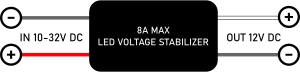
The Voltage Stabilizer (12V DC) is an electronic device designed to maintain a constant output voltage of 12V DC, regardless of fluctuations in input voltage or variations in load conditions. This ensures a stable and reliable power supply for sensitive electronic circuits, protecting them from potential damage caused by voltage instability.
Explore Projects Built with Voltage Stabilizer (12V DC)


Explore Projects Built with Voltage Stabilizer (12V DC)
Common Applications and Use Cases
- Powering microcontrollers, sensors, and other low-power devices
- Ensuring stable voltage for LED lighting systems
- Protecting sensitive electronic equipment from voltage fluctuations
- Use in automotive electronics to stabilize voltage from car batteries
- Powering communication devices and small appliances
Technical Specifications
Below are the key technical details and pin configuration for the Voltage Stabilizer (12V DC):
Key Technical Details
| Parameter | Value |
|---|---|
| Input Voltage Range | 14V - 24V DC |
| Output Voltage | 12V DC ± 0.5% |
| Maximum Output Current | 2A |
| Efficiency | ≥ 90% |
| Ripple Voltage | ≤ 50mV |
| Operating Temperature | -20°C to +70°C |
| Dimensions | 50mm x 25mm x 15mm |
| Weight | 30g |
Pin Configuration and Descriptions
| Pin Name | Description |
|---|---|
| VIN+ | Positive input voltage (14V - 24V DC) |
| VIN- | Negative input voltage (Ground) |
| VOUT+ | Positive stabilized output voltage (12V DC) |
| VOUT- | Negative stabilized output voltage (Ground) |
Usage Instructions
How to Use the Voltage Stabilizer in a Circuit
Connect the Input Voltage:
- Connect the positive terminal of the input power source (14V - 24V DC) to the
VIN+pin. - Connect the negative terminal of the input power source to the
VIN-pin.
- Connect the positive terminal of the input power source (14V - 24V DC) to the
Connect the Output Load:
- Connect the positive terminal of the load (e.g., microcontroller, LED strip) to the
VOUT+pin. - Connect the negative terminal of the load to the
VOUT-pin.
- Connect the positive terminal of the load (e.g., microcontroller, LED strip) to the
Verify Connections:
- Double-check all connections to ensure proper polarity and secure wiring.
Power On:
- Turn on the input power source. The stabilizer will regulate the input voltage and provide a steady 12V DC output.
Important Considerations and Best Practices
- Ensure the input voltage is within the specified range (14V - 24V DC). Exceeding this range may damage the stabilizer.
- Do not exceed the maximum output current of 2A to prevent overheating or failure.
- Use appropriate heat dissipation methods (e.g., heat sinks) if the stabilizer operates under high load conditions for extended periods.
- Keep the stabilizer away from moisture, dust, and extreme temperatures to ensure reliable operation.
- If using the stabilizer with an Arduino UNO or similar microcontroller, connect the
VOUT+pin to the Arduino'sVINpin and theVOUT-pin to the Arduino'sGNDpin.
Example: Using the Stabilizer with an Arduino UNO
Below is an example of how to connect the Voltage Stabilizer to an Arduino UNO and power an LED:
Circuit Connections
- Connect the stabilizer's
VOUT+to the Arduino'sVINpin. - Connect the stabilizer's
VOUT-to the Arduino'sGNDpin. - Connect an LED to one of the Arduino's digital pins (e.g., pin 13) with a current-limiting resistor.
Arduino Code
// Simple Arduino code to blink an LED connected to pin 13
// Ensure the Voltage Stabilizer is providing a stable 12V DC to the Arduino

void setup() {
  pinMode(13, OUTPUT); // Set pin 13 as an output
}

void loop() {
  digitalWrite(13, HIGH); // Turn the LED on
  delay(1000);            // Wait for 1 second
  digitalWrite(13, LOW);  // Turn the LED off
  delay(1000);            // Wait for 1 second
}
Troubleshooting and FAQs
Common Issues and Solutions
| Issue | Possible Cause | Solution |
|---|---|---|
| No output voltage | Incorrect input connections | Verify the polarity of the input voltage. |
| Output voltage is unstable | Input voltage is outside the specified range | Ensure input voltage is between 14V and 24V DC. |
| Stabilizer overheats | Load current exceeds 2A | Reduce the load or use a higher-capacity stabilizer. |
| Ripple voltage is too high | Poor input power quality | Use a capacitor at the input to filter noise. |
FAQs
Can I use the stabilizer with an AC power source?
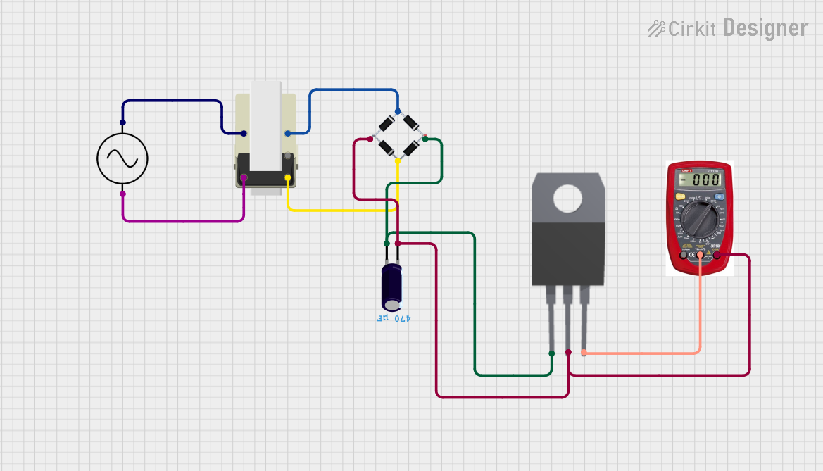
- No, the stabilizer is designed for DC input only. Use a rectifier and filter circuit to convert AC to DC before connecting to the stabilizer.
What happens if the input voltage drops below 14V?
- The stabilizer may fail to maintain a stable 12V output, and the output voltage may drop.
Can I connect multiple stabilizers in parallel for higher current?
- It is not recommended to connect stabilizers in parallel, as this may cause uneven current sharing and instability.
Is the stabilizer protected against short circuits?
- Some models may include short-circuit protection. Refer to the specific product datasheet for details.
By following this documentation, you can effectively use the Voltage Stabilizer (12V DC) to ensure a stable power supply for your electronic projects.