How to Use roborio 2.0: Examples, Pinouts, and Specs
Introduction
The RoboRIO 2.0, manufactured by National Indestrys (Part ID: 2.0), is a compact and powerful embedded controller designed specifically for robotics applications. It features a dual-core processor, a wide range of input/output (I/O) ports, and support for multiple programming languages, making it a versatile choice for controlling robotic systems. The RoboRIO 2.0 is widely used in robotics competitions, educational environments, and research projects due to its robust design and flexibility.
Explore Projects Built with roborio 2.0
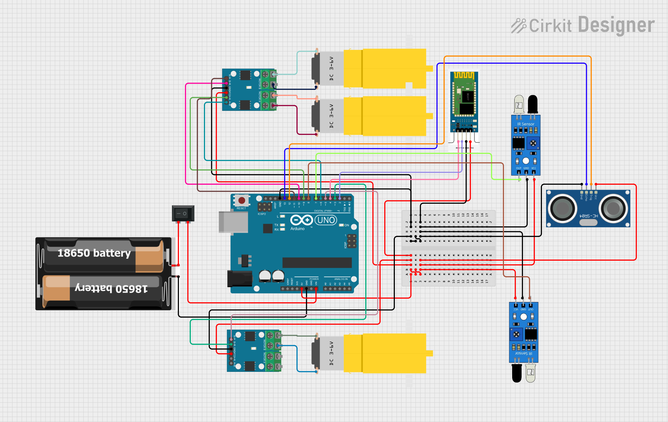
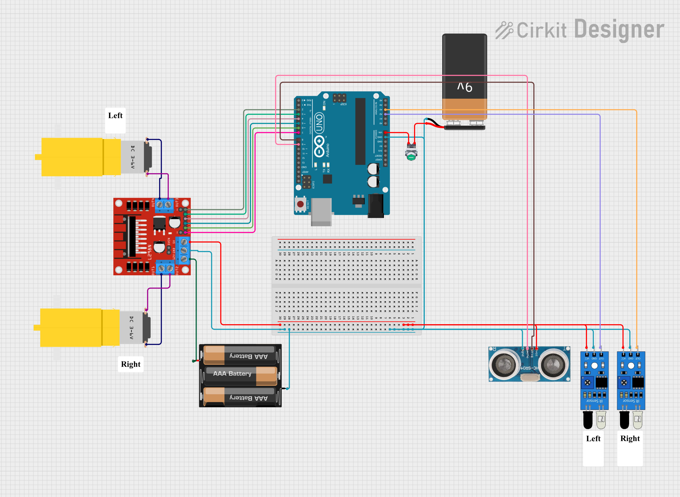
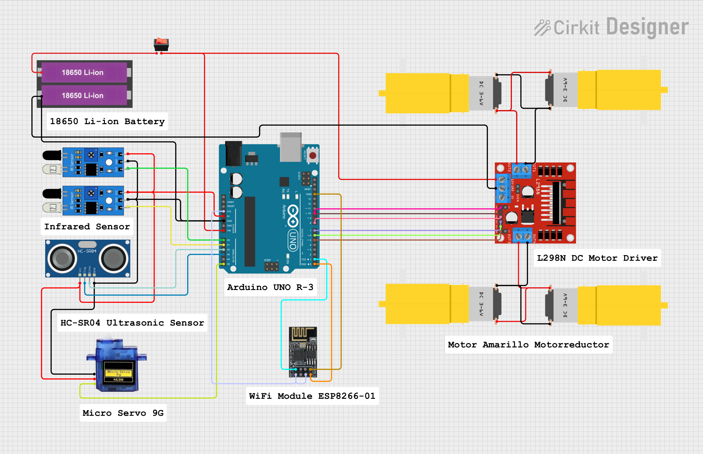

Explore Projects Built with roborio 2.0
Common Applications and Use Cases
- Robotics competitions (e.g., FIRST Robotics Competition)
- Educational robotics projects
- Research and development in robotics
- Industrial automation and control systems
- Prototyping and testing of robotic designs
Technical Specifications
Key Technical Details
| Specification | Value |
|---|---|
| Processor | Dual-core ARM Cortex-A9 |
| Clock Speed | 667 MHz |
| RAM | 512 MB DDR3 |
| Storage | 4 GB eMMC (expandable via USB or SD card) |
| Operating Voltage | 7V to 16V DC |
| Communication Interfaces | USB, Ethernet, CAN, RS-232, SPI, I2C |
| Digital I/O Ports | 10 |
| Analog Input Ports | 4 |
| PWM Output Channels | 10 |
| Relay Outputs | 4 |
| Dimensions | 5.5 x 3.5 x 1.5 inches |
| Weight | 0.5 lbs (approx.) |
| Supported Programming | LabVIEW, C++, Java, Python |
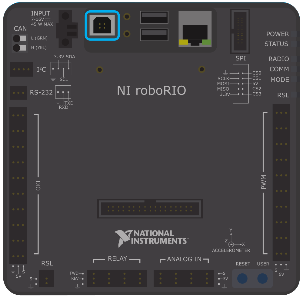
Pin Configuration and Descriptions
The RoboRIO 2.0 features multiple ports and connectors for interfacing with sensors, actuators, and other devices. Below is a summary of the key pin configurations:
Digital I/O Ports
| Pin Number | Function | Description |
|---|---|---|
| DIO1-DIO10 | Digital I/O | Configurable as input or output |
Analog Input Ports
| Pin Number | Function | Description |
|---|---|---|
| AI1-AI4 | Analog Input | Accepts 0-5V analog signals |
PWM Output Channels
| Pin Number | Function | Description |
|---|---|---|
| PWM1-PWM10 | PWM Output | Controls motor speed or servo position |
Communication Ports
| Port Type | Function | Description |
|---|---|---|
| USB | USB Host/Device | Connects to peripherals or programming |
| Ethernet | Network Interface | Enables wired communication |
| CAN | CAN Bus | Communicates with motor controllers |
| RS-232 | Serial Interface | Legacy serial communication |
| SPI/I2C | Communication | Interfaces with sensors and devices |
Usage Instructions
How to Use the RoboRIO 2.0 in a Circuit
Powering the RoboRIO 2.0:
- Connect a 12V DC power supply to the power input terminals.
- Ensure the power supply is within the operating voltage range (7V to 16V).
Connecting Sensors and Actuators:
- Use the digital I/O ports for digital sensors or switches.
- Connect analog sensors to the analog input ports (AI1-AI4).
- Attach motors or servos to the PWM output channels (PWM1-PWM10).
Programming the RoboRIO 2.0:
- Install the required software development environment (e.g., LabVIEW, C++, or Java).
- Connect the RoboRIO 2.0 to your computer via USB or Ethernet.
- Deploy your program to the RoboRIO 2.0 using the development environment.
Communication Setup:
- Use the Ethernet port for wired communication with a network or computer.
- Utilize the CAN bus for motor controllers or other CAN-enabled devices.
Important Considerations and Best Practices
- Power Supply: Ensure the power supply is stable and within the specified voltage range to avoid damage.
- Heat Management: The RoboRIO 2.0 may generate heat during operation. Ensure proper ventilation to prevent overheating.
- Firmware Updates: Regularly update the firmware to ensure compatibility with the latest software and features.
- Wiring: Double-check all connections to avoid short circuits or incorrect wiring.
Example Code for Arduino UNO Integration
While the RoboRIO 2.0 is a standalone controller, it can communicate with an Arduino UNO via serial communication. Below is an example of how to send data from an Arduino UNO to the RoboRIO 2.0:
// Arduino UNO Code: Sending data to RoboRIO 2.0 via Serial
void setup() {
  Serial.begin(9600); // Initialize serial communication at 9600 baud
}

void loop() {
  int sensorValue = analogRead(A0); // Read analog value from pin A0
  Serial.println(sensorValue); // Send the value to RoboRIO 2.0
  delay(100); // Wait for 100ms before sending the next value
}
On the RoboRIO 2.0, you can use a compatible programming language (e.g., Java or LabVIEW) to read the serial data and process it accordingly.
Troubleshooting and FAQs
Common Issues and Solutions
RoboRIO 2.0 Not Powering On:
- Cause: Insufficient or incorrect power supply.
- Solution: Verify the power supply voltage and connections.
No Communication with Computer:
- Cause: Incorrect USB or Ethernet connection.
- Solution: Check the cable connections and ensure the correct drivers are installed.
Sensors or Actuators Not Responding:
- Cause: Incorrect wiring or configuration.
- Solution: Double-check the wiring and ensure the ports are configured correctly in the software.
Overheating:
- Cause: Prolonged operation in a poorly ventilated environment.
- Solution: Improve ventilation or use a cooling fan.
FAQs
Q1: Can the RoboRIO 2.0 be programmed wirelessly?
A1: Yes, the RoboRIO 2.0 supports wireless programming via a compatible Wi-Fi adapter.
Q2: What programming languages are supported?
A2: The RoboRIO 2.0 supports LabVIEW, C++, Java, and Python.
Q3: Can I expand the storage capacity?
A3: Yes, you can expand the storage using a USB drive or SD card.
Q4: Is the RoboRIO 2.0 compatible with older RoboRIO accessories?
A4: Yes, the RoboRIO 2.0 is backward compatible with most accessories designed for the original RoboRIO.
Q5: How do I reset the RoboRIO 2.0?
A5: Press and hold the reset button for 5 seconds to perform a soft reset. For a factory reset, refer to the user manual.