How to Use Motor Driver Expansion Board Up side: Examples, Pinouts, and Specs
Introduction
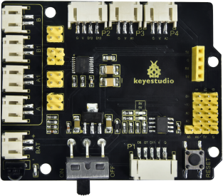
The Keyestudio 8833 Motor Driver Expansion Board is an add-on module designed to facilitate the control of motors in robotics and automation projects. It is compatible with microcontroller platforms such as the Arduino UNO. This board is particularly useful for hobbyists, educators, and prototyping professionals who require a reliable and easy-to-use solution for driving motors.
Explore Projects Built with Motor Driver Expansion Board Up side
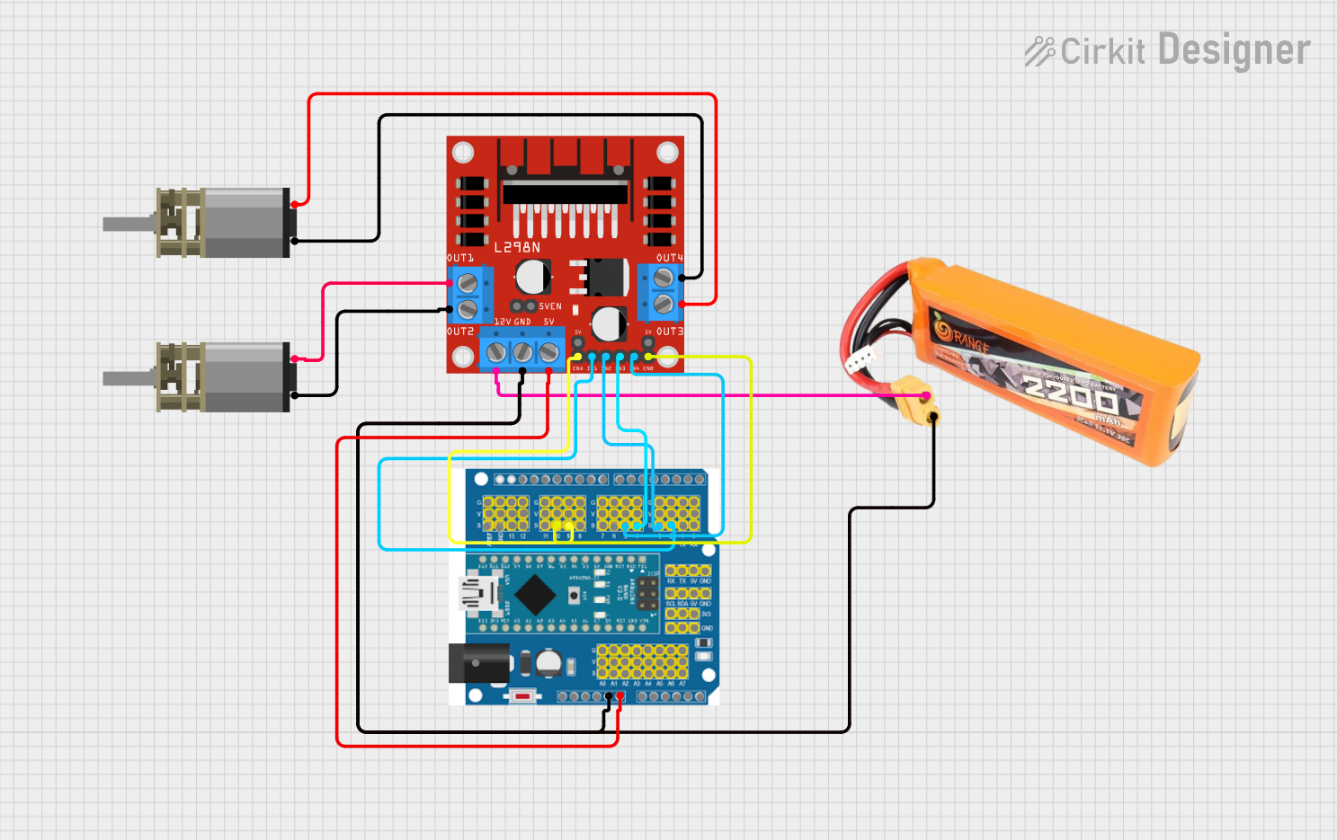
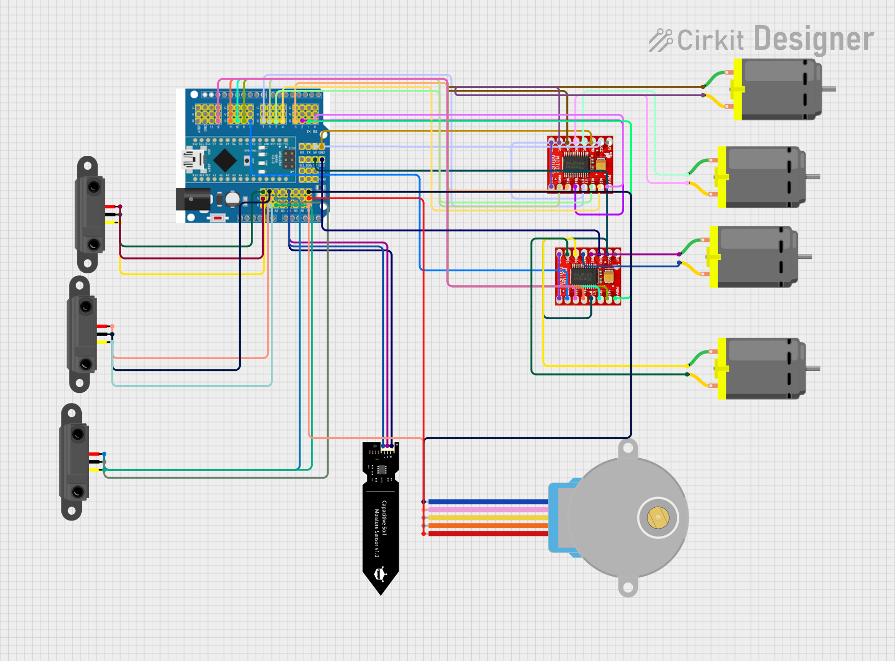


Explore Projects Built with Motor Driver Expansion Board Up side
Common Applications and Use Cases
- Robotics
- Automated machinery
- Educational projects
- DIY electronic vehicles
Technical Specifications
Key Technical Details
- Operating Voltage: 6V to 12V
- Driver: L298P dual full-bridge driver
- Drive Current: 2A (MAX single bridge)
- Logic Control Voltage: 5V (from Arduino)
- Control Signal Input Voltage: 2.3V-5V
- PWM Control: Compatible
Pin Configuration and Descriptions
| Pin Number | Description | Notes |
|---|---|---|
| 1 | Motor A Input 1 | Connect to digital output pin |
| 2 | Motor A Input 2 | Connect to digital output pin |
| 3 | Motor B Input 1 | Connect to digital output pin |
| 4 | Motor B Input 2 | Connect to digital output pin |
| 5 | Enable A | PWM input for speed control |
| 6 | Enable B | PWM input for speed control |
| 7 | 5V Output | Provides 5V from Arduino |
| 8 | Ground | Connect to Arduino GND |
| 9 | VM | Motor power supply (6V-12V) |
| 10 | VMS | Motor power supply sensing pin |
Usage Instructions
How to Use the Component in a Circuit
- Connect the motor(s) to the Motor Driver Expansion Board.
- Supply the board with 6V to 12V power to the VM pin.
- Connect the ground pin to the ground of the power supply and Arduino.
- Connect the Motor A and Motor B inputs to the digital output pins on the Arduino for direction control.
- Connect the Enable A and Enable B pins to PWM-capable pins on the Arduino for speed control.
- Upload the control code to the Arduino to start driving the motors.
Important Considerations and Best Practices
- Ensure the power supply voltage and current are within the specified limits to prevent damage.
- Use PWM signals for speed control to achieve variable motor speeds.
- Always disconnect the power supply before making or altering connections.
- Use proper decoupling capacitors to minimize voltage spikes that can occur when motors turn on or off.
Example Code for Arduino UNO
// Define motor control pins
#define MOTOR_A1 3
#define MOTOR_A2 4
#define MOTOR_B1 5
#define MOTOR_B2 6
#define ENABLE_A 9
#define ENABLE_B 10

void setup() {
  // Set motor control pins as outputs
  pinMode(MOTOR_A1, OUTPUT);
  pinMode(MOTOR_A2, OUTPUT);
  pinMode(MOTOR_B1, OUTPUT);
  pinMode(MOTOR_B2, OUTPUT);
  pinMode(ENABLE_A, OUTPUT);
  pinMode(ENABLE_B, OUTPUT);
}

void loop() {
  // Drive motor A forward at full speed
  digitalWrite(MOTOR_A1, HIGH);
  digitalWrite(MOTOR_A2, LOW);
  analogWrite(ENABLE_A, 255); // Full speed

  // Drive motor B backward at half speed
  digitalWrite(MOTOR_B1, LOW);
  digitalWrite(MOTOR_B2, HIGH);
  analogWrite(ENABLE_B, 127); // Half speed

  delay(2000); // Run motors for 2 seconds

  // Stop both motors
  digitalWrite(MOTOR_A1, LOW);
  digitalWrite(MOTOR_A2, LOW);
  digitalWrite(MOTOR_B1, LOW);
  digitalWrite(MOTOR_B2, LOW);
  analogWrite(ENABLE_A, 0); // Stop motor A
  analogWrite(ENABLE_B, 0); // Stop motor B

  delay(2000); // Wait for 2 seconds
}
Troubleshooting and FAQs
Common Issues Users Might Face
- Motor not running: Check power supply and connections to the board.
- Motor runs only in one direction: Verify the logic signals to the input pins.
- Inconsistent motor speed: Ensure PWM signals are correctly applied to the Enable pins.
Solutions and Tips for Troubleshooting
- Double-check wiring against the pin configuration table.
- Use a multimeter to verify the voltage at the motor and logic inputs.
- Ensure the Arduino code matches the intended motor behavior.
FAQs
Q: Can I control stepper motors with this board? A: No, the 8833 Motor Driver is designed for DC motors. Stepper motors require a different type of driver.
Q: What is the maximum current the board can handle? A: The board can handle a maximum of 2A per motor channel.
Q: Can I use this board with a 3.3V logic level microcontroller? A: Yes, the control signal input voltage range is 2.3V-5V, which accommodates 3.3V logic levels.
Q: How do I adjust the speed of the motors? A: Speed control is achieved by applying PWM signals to the Enable A and Enable B pins.
For further assistance, please refer to the Keyestudio community forums or contact technical support.