Cirkit Designer Logo
Cirkit Designer
Your all-in-one circuit design IDE
Home / 
Component Documentation

How to Use Vietduino ESP32: Examples, Pinouts, and Specs

Image of Vietduino ESP32
Cirkit Designer LogoDesign with Vietduino ESP32 in Cirkit Designer

Introduction

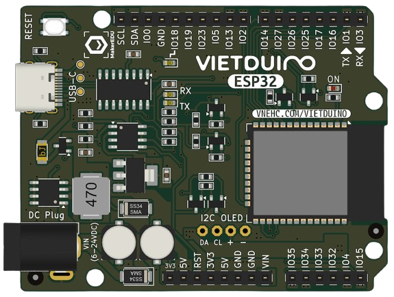
The Vietduino ESP32, manufactured by MakerEdu.vn (Part ID: ESP32), is a powerful and versatile microcontroller board built around the ESP32 chip. It features integrated Wi-Fi and Bluetooth connectivity, making it an ideal choice for Internet of Things (IoT) applications. With its dual-core processor, extensive GPIO options, and robust performance, the Vietduino ESP32 is suitable for a wide range of projects, from smart home devices to industrial automation.

Explore Projects Built with Vietduino ESP32

Use Cirkit Designer to design, explore, and prototype these projects online. Some projects support real-time simulation. Click "Open Project" to start designing instantly!
ESP32-Based Environmental Monitoring System with Water Flow Sensing
Image of Water: A project utilizing Vietduino ESP32 in a practical application
This circuit features an ESP32 Devkit V1 microcontroller connected to a DHT22 temperature and humidity sensor and a water flow sensor. The ESP32 reads environmental data from the DHT22 via a digital input pin (D33) and monitors water flow through the water flow sensor connected to another digital input pin (D23). The ESP32 is powered through its VIN pin, and both sensors are powered by the ESP32's 3V3 output, with common ground connections.
Cirkit Designer LogoOpen Project in Cirkit Designer
ESP32-Based Detection System with IR Sensors and Servo Actuators
Image of smart parking system: A project utilizing Vietduino ESP32 in a practical application
This circuit features an ESP32 microcontroller connected to multiple peripherals. Four IR sensors are interfaced with the ESP32's GPIO pins (D34, D32, D33, D27) to likely detect objects or motion. Two servo motors are controlled by the ESP32 (via pins D14 and D15), and an I2C LCD screen is connected for display purposes (using SDA and SCL lines on pins D22 and D21). All components share a common ground and are powered by a shared voltage supply.
Cirkit Designer LogoOpen Project in Cirkit Designer
ESP32-Based Environmental Monitoring and Alert System with Solar Charging
Image of mark: A project utilizing Vietduino ESP32 in a practical application
This circuit features an ESP32 Devkit V1 microcontroller connected to various sensors and modules for monitoring and communication purposes. It includes an MQ-2 gas sensor and a DHT11 temperature and humidity sensor, both interfaced with the ESP32 for environmental data collection. The circuit is powered by a 12V battery, regulated to 5V by step-down converters, and includes a solar charge controller connected to a solar panel for battery charging, a UPS module for power management, and a SIM900A module for GSM communication. Additionally, there is a WS2812 RGB LED strip for visual feedback and a piezo buzzer for audio alerts, both controlled by the ESP32.
Cirkit Designer LogoOpen Project in Cirkit Designer
ESP32 and Logic Level Converter-Based Wi-Fi Controlled Interface
Image of Toshiba AC ESP32 devkit v1: A project utilizing Vietduino ESP32 in a practical application
This circuit features an ESP32 Devkit V1 microcontroller connected to a Bi-Directional Logic Level Converter, which facilitates voltage level shifting between the ESP32 and external components. The ESP32 is powered through its VIN pin via an alligator clip cable, and the logic level converter is connected to various pins on the ESP32 to manage different voltage levels for communication.
Cirkit Designer LogoOpen Project in Cirkit Designer

Explore Projects Built with Vietduino ESP32

Use Cirkit Designer to design, explore, and prototype these projects online. Some projects support real-time simulation. Click "Open Project" to start designing instantly!
Image of Water: A project utilizing Vietduino ESP32 in a practical application
ESP32-Based Environmental Monitoring System with Water Flow Sensing
This circuit features an ESP32 Devkit V1 microcontroller connected to a DHT22 temperature and humidity sensor and a water flow sensor. The ESP32 reads environmental data from the DHT22 via a digital input pin (D33) and monitors water flow through the water flow sensor connected to another digital input pin (D23). The ESP32 is powered through its VIN pin, and both sensors are powered by the ESP32's 3V3 output, with common ground connections.
Cirkit Designer LogoOpen Project in Cirkit Designer
Image of smart parking system: A project utilizing Vietduino ESP32 in a practical application
ESP32-Based Detection System with IR Sensors and Servo Actuators
This circuit features an ESP32 microcontroller connected to multiple peripherals. Four IR sensors are interfaced with the ESP32's GPIO pins (D34, D32, D33, D27) to likely detect objects or motion. Two servo motors are controlled by the ESP32 (via pins D14 and D15), and an I2C LCD screen is connected for display purposes (using SDA and SCL lines on pins D22 and D21). All components share a common ground and are powered by a shared voltage supply.
Cirkit Designer LogoOpen Project in Cirkit Designer
Image of mark: A project utilizing Vietduino ESP32 in a practical application
ESP32-Based Environmental Monitoring and Alert System with Solar Charging
This circuit features an ESP32 Devkit V1 microcontroller connected to various sensors and modules for monitoring and communication purposes. It includes an MQ-2 gas sensor and a DHT11 temperature and humidity sensor, both interfaced with the ESP32 for environmental data collection. The circuit is powered by a 12V battery, regulated to 5V by step-down converters, and includes a solar charge controller connected to a solar panel for battery charging, a UPS module for power management, and a SIM900A module for GSM communication. Additionally, there is a WS2812 RGB LED strip for visual feedback and a piezo buzzer for audio alerts, both controlled by the ESP32.
Cirkit Designer LogoOpen Project in Cirkit Designer
Image of Toshiba AC ESP32 devkit v1: A project utilizing Vietduino ESP32 in a practical application
ESP32 and Logic Level Converter-Based Wi-Fi Controlled Interface
This circuit features an ESP32 Devkit V1 microcontroller connected to a Bi-Directional Logic Level Converter, which facilitates voltage level shifting between the ESP32 and external components. The ESP32 is powered through its VIN pin via an alligator clip cable, and the logic level converter is connected to various pins on the ESP32 to manage different voltage levels for communication.
Cirkit Designer LogoOpen Project in Cirkit Designer

Common Applications and Use Cases

  • IoT devices and smart home automation
  • Wireless sensor networks
  • Robotics and control systems
  • Data logging and remote monitoring
  • Wearable technology
  • Prototyping and educational projects

Technical Specifications

The Vietduino ESP32 offers a rich set of features and capabilities. Below are its key technical specifications:

Specification Details
Microcontroller ESP32 (dual-core Xtensa LX6 processor)
Clock Speed Up to 240 MHz
Flash Memory 4 MB (varies by model)
SRAM 520 KB
Connectivity Wi-Fi 802.11 b/g/n, Bluetooth v4.2 + BLE
Operating Voltage 3.3V
Input Voltage Range 5V (via USB) or 7-12V (via VIN pin)
GPIO Pins 34 (multipurpose, including ADC, DAC, PWM, I2C, SPI, UART)
ADC Channels 18 (12-bit resolution)
DAC Channels 2
PWM Channels 16
Communication Interfaces UART, SPI, I2C, I2S, CAN, Ethernet MAC
Power Consumption Ultra-low power consumption in deep sleep mode (as low as 10 µA)
Dimensions 58 mm x 25 mm

Pin Configuration and Descriptions

The Vietduino ESP32 has a variety of pins for different functionalities. Below is the pinout description:

Pin Name Type Description
VIN Power Input External power input (7-12V)
3V3 Power Output 3.3V regulated output
GND Ground Ground connection
GPIO0-GPIO39 GPIO General-purpose input/output pins (multipurpose: ADC, DAC, PWM, etc.)
EN Reset Enable pin to reset the microcontroller
TXD0, RXD0 UART Default UART communication pins
SCL, SDA I2C I2C communication pins (clock and data)
MOSI, MISO, SCK SPI SPI communication pins (Master Out Slave In, Master In Slave Out, Clock)
A0-A17 ADC Analog-to-digital converter pins (12-bit resolution)
DAC1, DAC2 DAC Digital-to-analog converter pins

Usage Instructions

How to Use the Vietduino ESP32 in a Circuit

  1. Powering the Board:

    • Connect the board to a computer or USB power source using a micro-USB cable.
    • Alternatively, supply 7-12V to the VIN pin for external power.
  2. Programming the Board:

    • Install the Arduino IDE and add the ESP32 board support package.
    • Select "Vietduino ESP32" or the appropriate ESP32 board from the Tools menu.
    • Connect the board to your computer via USB and select the correct COM port.
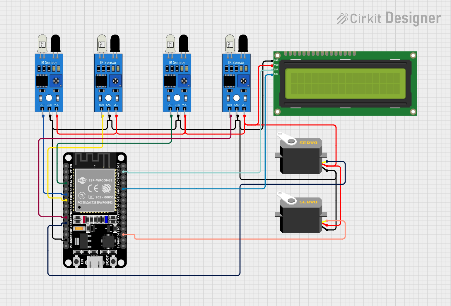
  3. Connecting Peripherals:

    • Use the GPIO pins to connect sensors, actuators, or other peripherals.
    • Ensure that the voltage levels of connected devices are compatible with the 3.3V logic of the ESP32.
  4. Uploading Code:

    • Write your code in the Arduino IDE or another compatible environment.
    • Click the upload button to flash the code to the board.

Important Considerations and Best Practices

  • Voltage Levels: The GPIO pins operate at 3.3V. Avoid connecting 5V devices directly to the pins without a level shifter.
  • Deep Sleep Mode: Use deep sleep mode to conserve power in battery-powered applications.
  • Pin Multiplexing: Many pins have multiple functions. Refer to the ESP32 datasheet to avoid conflicts when using peripherals.
  • Wi-Fi and Bluetooth: Avoid placing the board near metal objects or enclosures that may interfere with wireless signals.

Example Code for Arduino UNO Integration

Below is an example of how to use the Vietduino ESP32 to read a temperature sensor and send the data over Wi-Fi:

#include <WiFi.h> // Include the Wi-Fi library

// Replace with your network credentials
const char* ssid = "Your_SSID";
const char* password = "Your_PASSWORD";

void setup() {
  Serial.begin(115200); // Initialize serial communication
  WiFi.begin(ssid, password); // Connect to Wi-Fi

  // Wait for connection
  while (WiFi.status() != WL_CONNECTED) {
    delay(1000);
    Serial.println("Connecting to Wi-Fi...");
  }
  Serial.println("Connected to Wi-Fi");
}

void loop() {
  // Example: Read a sensor value (replace with actual sensor code)
  int sensorValue = analogRead(34); // Read from GPIO34 (ADC1 channel)
  Serial.print("Sensor Value: ");
  Serial.println(sensorValue);

  delay(1000); // Wait for 1 second
}

Troubleshooting and FAQs

Common Issues and Solutions

  1. Board Not Detected by Computer:

    • Ensure the USB cable is functional and supports data transfer.
    • Install the correct USB-to-serial driver for the ESP32.
  2. Code Upload Fails:

    • Check that the correct COM port and board are selected in the Arduino IDE.
    • Press and hold the "BOOT" button on the board while uploading the code.
  3. Wi-Fi Connection Issues:

    • Verify the SSID and password are correct.
    • Ensure the router is within range and not blocking the ESP32.
  4. GPIO Pin Not Working:

    • Confirm the pin is not being used for another function (e.g., UART, SPI).
    • Check for wiring issues or incorrect voltage levels.

FAQs

Q: Can I use 5V sensors with the Vietduino ESP32?
A: The GPIO pins operate at 3.3V. Use a level shifter to safely interface with 5V sensors.

Q: How do I reset the board?
A: Press the "EN" button on the board to reset the microcontroller.

Q: What is the maximum Wi-Fi range?
A: The range depends on environmental factors but typically extends up to 50 meters indoors and 200 meters outdoors.

Q: Can I use the Vietduino ESP32 with MicroPython?
A: Yes, the ESP32 supports MicroPython. Flash the MicroPython firmware to the board to get started.