How to Use DC motor with Gear: Examples, Pinouts, and Specs
Introduction
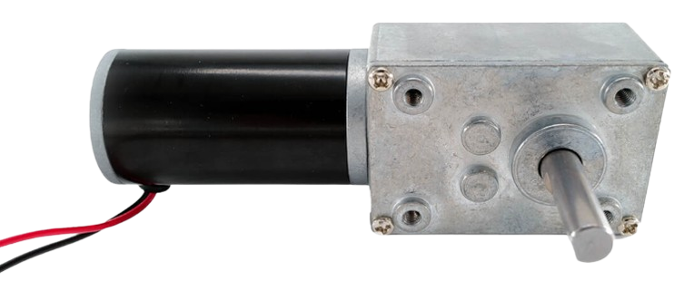
A DC motor with an integrated gear system is an electromechanical device that converts electrical energy into mechanical energy. The addition of a gear system allows the motor to deliver increased torque while reducing its speed, making it ideal for applications requiring precise control and high torque at low speeds. These motors are widely used in robotics, automation systems, conveyor belts, and other machinery where controlled motion is essential.
Explore Projects Built with DC motor with Gear

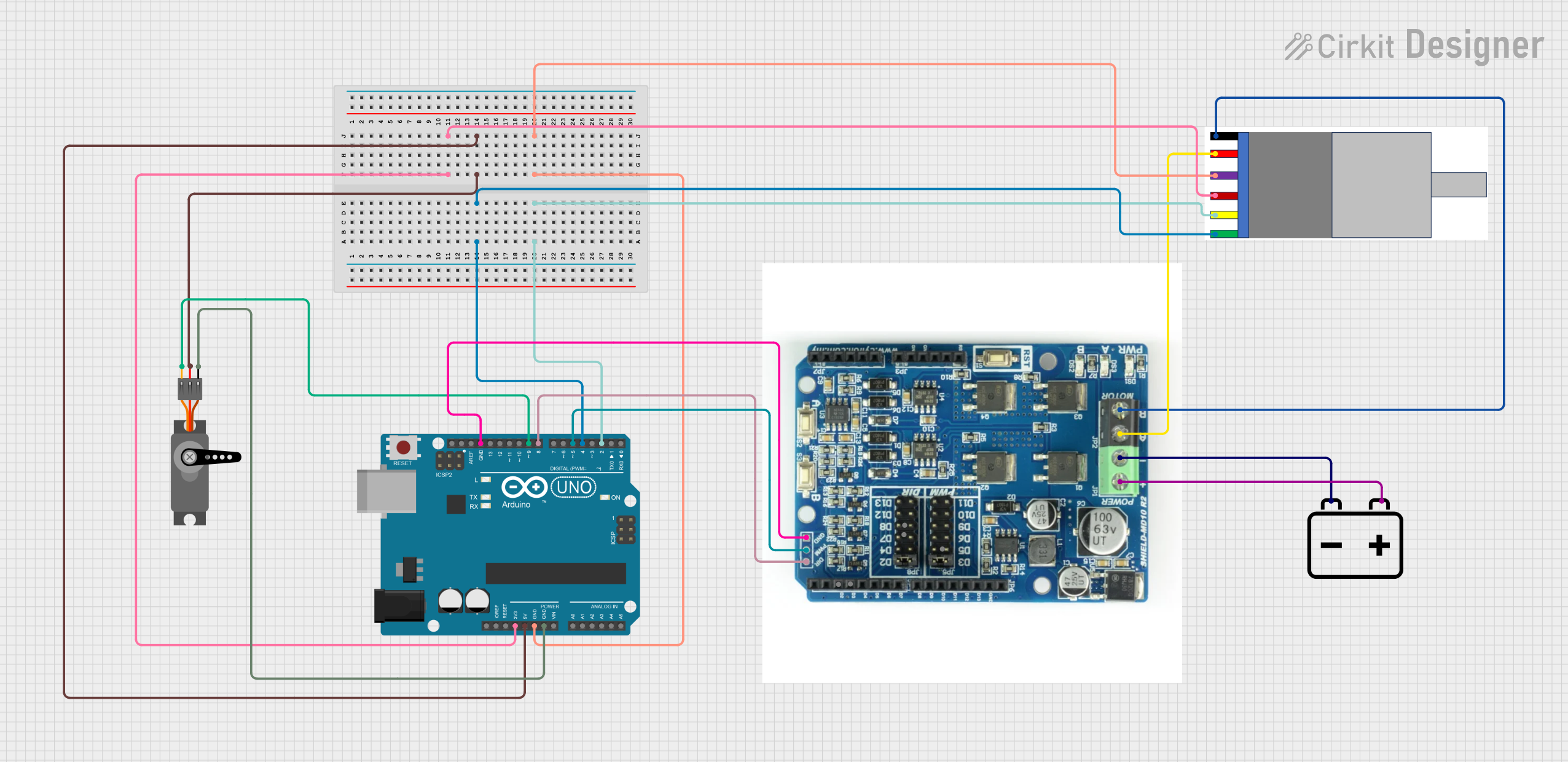
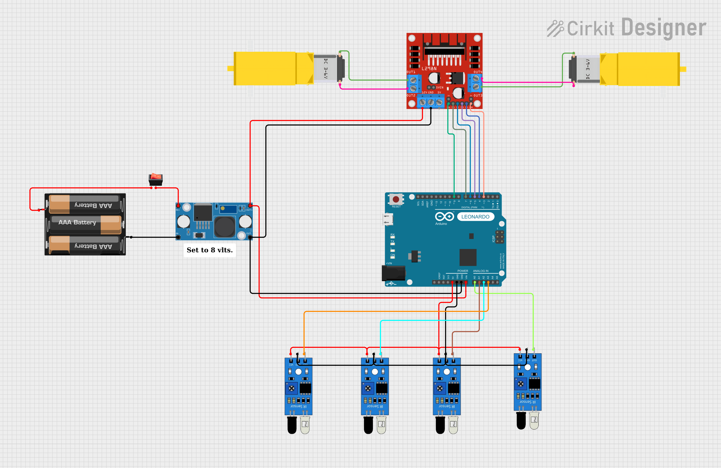
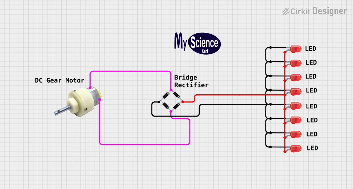
Explore Projects Built with DC motor with Gear
Common Applications and Use Cases
- Robotics (e.g., robotic arms, mobile robots)
- Conveyor systems
- Automated door mechanisms
- Electric vehicles
- Industrial machinery
- Precision tools and equipment
Technical Specifications
Below are the general technical specifications for a typical DC motor with a gear system. Note that specific values may vary depending on the model and manufacturer.
General Specifications
| Parameter | Value |
|---|---|
| Operating Voltage | 6V to 24V |
| Rated Current | 0.5A to 2A (depending on load) |
| Stall Current | 2A to 5A |
| Output Speed (No Load) | 10 RPM to 500 RPM |
| Torque | 1 kg·cm to 50 kg·cm |
| Gear Ratio | 10:1 to 200:1 |
| Motor Type | Brushed DC Motor |
| Shaft Diameter | 4mm to 6mm |
| Operating Temperature | -10°C to 60°C |
Pin Configuration and Descriptions
Most DC motors with gears have two terminals for electrical connections. These terminals are typically labeled as follows:
| Pin Name | Description |
|---|---|
| V+ | Positive terminal for power supply |
| V- | Negative terminal (ground) for power supply |
For bidirectional control, an H-bridge motor driver is often used to reverse the polarity of the voltage applied to the motor.
Usage Instructions
How to Use the Component in a Circuit
- Power Supply: Connect the motor terminals to a DC power source within the specified voltage range (e.g., 6V to 24V). Ensure the power supply can provide sufficient current for the motor's operation.
- Motor Driver: Use a motor driver (e.g., L298N, L293D, or an H-bridge module) to control the motor's speed and direction. The driver allows for PWM (Pulse Width Modulation) control and bidirectional operation.
- Microcontroller Integration: If using a microcontroller like an Arduino UNO, connect the motor driver to the microcontroller's PWM and digital pins for speed and direction control.
Important Considerations and Best Practices
- Current Rating: Ensure the power supply and motor driver can handle the motor's stall current to avoid damage.
- Heat Dissipation: Prolonged operation at high torque may cause the motor to heat up. Use heat sinks or allow cooling periods to prevent overheating.
- Gearbox Maintenance: Avoid applying excessive force to the motor shaft, as this can damage the gearbox.
- Noise and Vibration: Secure the motor firmly in place to minimize noise and vibration during operation.
Example: Controlling a DC Motor with Gear Using Arduino UNO
Below is an example of how to control a DC motor with a gear system using an Arduino UNO and an L298N motor driver.
// Example: Controlling a DC motor with gear using Arduino UNO and L298N driver

// Define motor control pins
const int ENA = 9;  // PWM pin for speed control
const int IN1 = 8;  // Direction control pin 1
const int IN2 = 7;  // Direction control pin 2

void setup() {
  // Set motor control pins as outputs
  pinMode(ENA, OUTPUT);
  pinMode(IN1, OUTPUT);
  pinMode(IN2, OUTPUT);
}

void loop() {
  // Rotate motor in forward direction
  digitalWrite(IN1, HIGH);  // Set IN1 high
  digitalWrite(IN2, LOW);   // Set IN2 low
  analogWrite(ENA, 150);    // Set speed (0-255)

  delay(3000);  // Run motor for 3 seconds

  // Stop the motor
  digitalWrite(IN1, LOW);   // Set IN1 low
  digitalWrite(IN2, LOW);   // Set IN2 low
  analogWrite(ENA, 0);      // Set speed to 0

  delay(1000);  // Wait for 1 second

  // Rotate motor in reverse direction
  digitalWrite(IN1, LOW);   // Set IN1 low
  digitalWrite(IN2, HIGH);  // Set IN2 high
  analogWrite(ENA, 150);    // Set speed (0-255)

  delay(3000);  // Run motor for 3 seconds

  // Stop the motor
  digitalWrite(IN1, LOW);   // Set IN1 low
  digitalWrite(IN2, LOW);   // Set IN2 low
  analogWrite(ENA, 0);      // Set speed to 0

  delay(1000);  // Wait for 1 second
}
Troubleshooting and FAQs
Common Issues and Solutions
Motor Does Not Spin:
- Check the power supply voltage and current rating.
- Verify the motor driver connections and ensure the control signals are correct.
- Inspect the motor terminals for loose or damaged wires.
Motor Spins in Only One Direction:
- Ensure both direction control pins (e.g., IN1 and IN2) are properly connected.
- Verify the motor driver is functioning correctly.
Motor Overheats:
- Reduce the load on the motor or use a motor with a higher torque rating.
- Allow the motor to cool down periodically during extended operation.
Excessive Noise or Vibration:
- Check for loose mounting or misalignment of the motor.
- Inspect the gearbox for wear or damage.
FAQs
Q: Can I run the motor directly from an Arduino pin?
A: No, the Arduino pins cannot supply enough current to drive the motor. Always use a motor driver or external power source.
Q: How do I calculate the required torque for my application?
A: Determine the load's weight and the distance from the motor shaft. Use the formula:
Torque (kg·cm) = Load (kg) × Distance (cm).
Q: Can I use this motor for high-speed applications?
A: DC motors with gears are optimized for high torque and low speed. For high-speed applications, consider using a standard DC motor without a gearbox.