How to Use Led Module Green: Examples, Pinouts, and Specs
Introduction
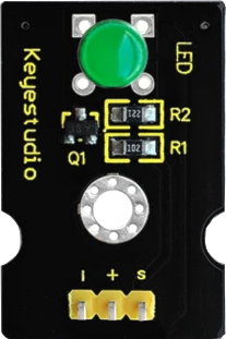
The Keyestudio LED Module Green (Part ID: KS0232) is a compact and efficient module featuring a green LED that emits bright green light when powered. It is designed for ease of use in a variety of electronic projects, making it ideal for beginners and professionals alike. This module is commonly used as an indicator, status light, or part of a display system in circuits. Its simple design allows for quick integration into breadboards, microcontroller projects, and other electronic systems.
Explore Projects Built with Led Module Green

Explore Projects Built with Led Module Green
Common Applications
- Power or status indicators in electronic devices
- Visual feedback in microcontroller projects
- Signal or warning lights in control systems
- Educational and prototyping purposes
Technical Specifications
The following table outlines the key technical details of the Keyestudio LED Module Green:
| Parameter | Value |
|---|---|
| Operating Voltage | 3.3V to 5V |
| Operating Current | 20mA (typical) |
| LED Color | Green |
| LED Wavelength | 520-530 nm |
| Module Dimensions | 18mm x 15mm x 8mm |
| Mounting Type | PCB or breadboard compatible |
Pin Configuration
The module has a simple 3-pin interface, as described in the table below:
| Pin | Name | Description |
|---|---|---|
| 1 | Signal (S) | Input pin to control the LED (connect to microcontroller or signal source) |
| 2 | VCC | Power supply pin (3.3V to 5V) |
| 3 | GND | Ground connection |
Usage Instructions
How to Use the LED Module Green in a Circuit
- Power the Module: Connect the
VCCpin to a 3.3V or 5V power source and theGNDpin to the ground of your circuit. - Control the LED: Use the
Signal (S)pin to control the LED. This pin can be connected to a microcontroller's GPIO pin or a simple switch. When the signal pin is HIGH, the LED will light up. - Resistor Consideration: The module includes an onboard current-limiting resistor, so no external resistor is required for typical use.
Important Considerations
- Voltage Range: Ensure the input voltage does not exceed 5V to avoid damaging the module.
- Polarity: Double-check the connections to avoid reversing the polarity, which could damage the LED.
- Signal Control: When using a microcontroller, configure the GPIO pin as an output to control the LED.
Example: Connecting to an Arduino UNO
Below is an example of how to connect and control the Keyestudio LED Module Green using an Arduino UNO:
Circuit Connections
- Connect the
Signal (S)pin of the module to Arduino digital pin 8. - Connect the
VCCpin of the module to the Arduino's 5V pin. - Connect the
GNDpin of the module to the Arduino's GND pin.
Arduino Code
// Example code to control the Keyestudio LED Module Green (KS0232)

// Define the pin connected to the LED module
const int ledPin = 8;

void setup() {
  // Set the LED pin as an output
  pinMode(ledPin, OUTPUT);
}

void loop() {
  // Turn the LED on
  digitalWrite(ledPin, HIGH);
  delay(1000); // Wait for 1 second

  // Turn the LED off
  digitalWrite(ledPin, LOW);
  delay(1000); // Wait for 1 second
}
Best Practices
- Use a breadboard for prototyping to ensure secure connections.
- Avoid prolonged operation at maximum current to extend the LED's lifespan.
- If using multiple LED modules, ensure the power supply can handle the total current draw.
Troubleshooting and FAQs
Common Issues and Solutions
LED Does Not Light Up
- Cause: Incorrect wiring or reversed polarity.
- Solution: Verify the connections and ensure the
VCCandGNDpins are correctly connected.
LED Flickers or Is Dim
- Cause: Insufficient power supply or loose connections.
- Solution: Check the power source and ensure all connections are secure.
Module Overheats
- Cause: Excessive voltage or current.
- Solution: Ensure the input voltage is within the 3.3V to 5V range.
FAQs
Q: Can I use this module with a 3.3V microcontroller like the ESP32?
A: Yes, the module is compatible with 3.3V systems. Connect the VCC pin to the 3.3V output of your microcontroller.
Q: Do I need an external resistor for this module?
A: No, the module includes an onboard current-limiting resistor, so no additional resistor is required.
Q: Can I use PWM to control the brightness of the LED?
A: Yes, you can connect the Signal (S) pin to a PWM-capable GPIO pin on your microcontroller to adjust the LED brightness.
Q: Is the module waterproof?
A: No, the module is not waterproof. Avoid exposing it to moisture or liquids.
By following this documentation, you can effectively integrate the Keyestudio LED Module Green (KS0232) into your projects and troubleshoot any issues that arise.