
How to Use RJ45 Jack: Examples, Pinouts, and Specs
 Design with RJ45 Jack in Cirkit Designer
Introduction
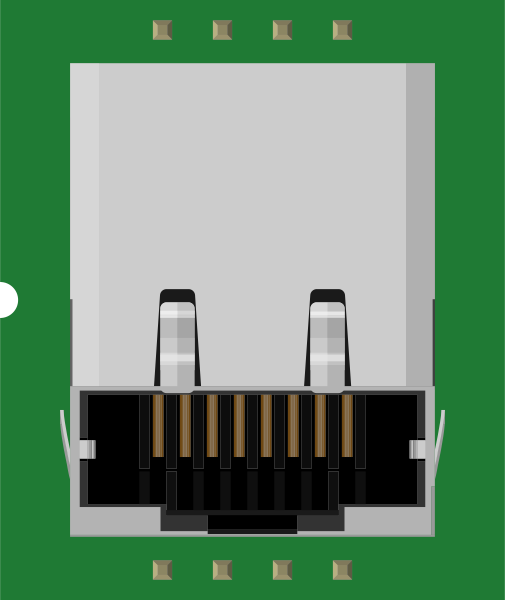
The RJ45 Jack (Manufacturer: SparkFun, Part ID: PRT-00643) is a standardized connector widely used in Ethernet networking. It facilitates the connection of network cables to devices such as computers, routers, switches, and other networking equipment. This component is essential for establishing wired network connections, ensuring reliable data transmission in both residential and industrial environments.
Explore Projects Built with RJ45 Jack
 Open Project in Cirkit Designer
 Open Project in Cirkit Designer
 Open Project in Cirkit Designer
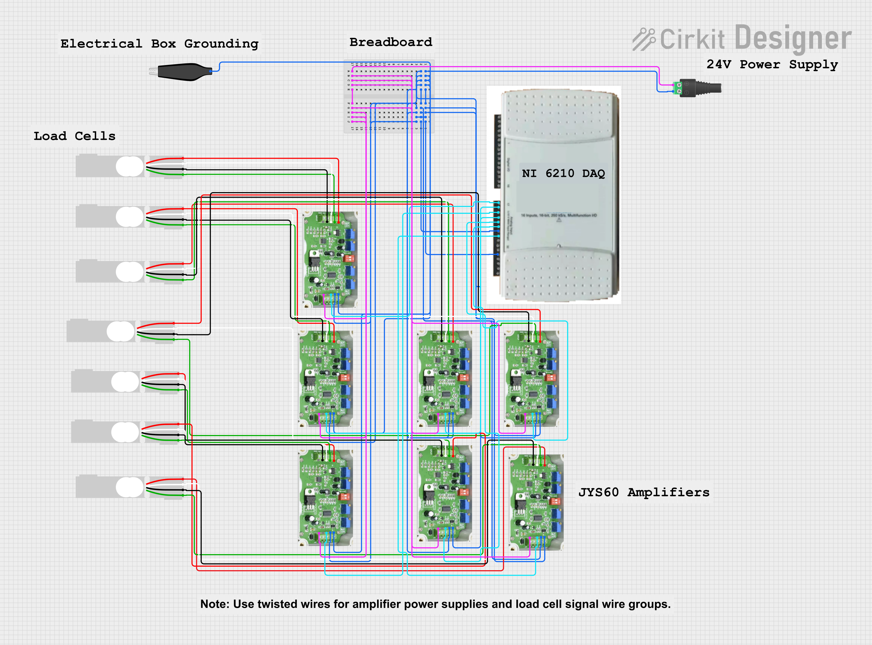 Open Project in Cirkit Designer
Explore Projects Built with RJ45 Jack
Open Project in Cirkit DesignerOpen Project in Cirkit DesignerOpen Project in Cirkit DesignerOpen Project in Cirkit DesignerCommon Applications and Use Cases
- Ethernet networking for home and office environments
- Internet of Things (IoT) devices requiring wired connectivity
- Industrial automation systems
- Network testing and diagnostics
- Embedded systems with Ethernet communication capabilities
Technical Specifications
The RJ45 Jack (PRT-00643) is designed to meet industry standards for Ethernet connectivity. Below are its key technical details:
General Specifications
| Parameter | Value |
|---|---|
| Manufacturer | SparkFun |
| Part ID | PRT-00643 |
| Connector Type | RJ45 |
| Number of Pins | 8 |
| Supported Standards | Ethernet (10/100/1000 Mbps) |
| Mounting Type | Through-hole |
| Shielding | Yes |
| Operating Temperature | -40°C to +85°C |
Pin Configuration and Descriptions
The RJ45 Jack has 8 pins, corresponding to the 8 conductors in an Ethernet cable. The pinout follows the T568A/B wiring standards.
| Pin Number | Signal Name | Description |
|---|---|---|
| 1 | TX+ | Transmit Data Positive |
| 2 | TX- | Transmit Data Negative |
| 3 | RX+ | Receive Data Positive |
| 4 | BI_D3+ | Bidirectional Data Pair 3 Positive |
| 5 | BI_D3- | Bidirectional Data Pair 3 Negative |
| 6 | RX- | Receive Data Negative |
| 7 | BI_D4+ | Bidirectional Data Pair 4 Positive |
| 8 | BI_D4- | Bidirectional Data Pair 4 Negative |
Usage Instructions
How to Use the RJ45 Jack in a Circuit
Mounting the Component:
- The RJ45 Jack is a through-hole component. Insert it into the PCB and solder the pins securely.
- Ensure proper alignment to avoid miswiring.
Connecting Ethernet Cables:
- Use a standard Ethernet cable (Cat5e, Cat6, or higher) with an RJ45 plug.
- Insert the plug into the jack until it clicks into place.
Wiring the Pins:
- Follow the T568A or T568B wiring standard to connect the pins to the appropriate signals on your PCB.
- Use differential pairs (TX+/TX-, RX+/RX-) for data transmission and reception.
Power and Grounding:
- If the RJ45 Jack includes shielding, connect the shield pin to the ground plane for improved EMI performance.
Important Considerations and Best Practices
- Signal Integrity: Use proper PCB trace routing techniques to maintain signal integrity, especially for high-speed Ethernet signals.
- ESD Protection: Add ESD protection diodes to the data lines to safeguard against electrostatic discharge.
- PoE (Power over Ethernet): If using PoE, ensure the circuit design complies with IEEE 802.3af/at standards.
- Testing: Verify connections with a network cable tester before deploying the circuit.
Example: Connecting to an Arduino UNO
The RJ45 Jack can be used with an Ethernet shield to enable network connectivity for an Arduino UNO. Below is an example code snippet for using the Ethernet library to establish a basic connection:
#include <SPI.h>
#include <Ethernet.h>

// MAC address for the Ethernet shield
byte mac[] = { 0xDE, 0xAD, 0xBE, 0xEF, 0xFE, 0xED };

// IP address for the Arduino (adjust as needed)
IPAddress ip(192, 168, 1, 177);

// Initialize the Ethernet server on port 80
EthernetServer server(80);

void setup() {
  // Start the Ethernet connection
  Ethernet.begin(mac, ip);

  // Start the server
  server.begin();

  // Print the IP address to the Serial Monitor
  Serial.begin(9600);
  Serial.print("Server is at ");
  Serial.println(Ethernet.localIP());
}

void loop() {
  // Listen for incoming clients
  EthernetClient client = server.available();
  if (client) {
    // Handle client requests
    server.write("Hello, Ethernet!");
    delay(1);
    client.stop();
  }
}
Troubleshooting and FAQs
Common Issues and Solutions
No Network Connectivity:
- Cause: Incorrect wiring or loose connections.
- Solution: Verify the pinout and ensure the Ethernet cable is securely connected.
Intermittent Data Transmission:
- Cause: Poor soldering or signal integrity issues.
- Solution: Inspect solder joints and use proper PCB trace routing techniques.
High EMI Interference:
- Cause: Lack of shielding or improper grounding.
- Solution: Connect the shield pin to the ground plane and use shielded Ethernet cables.
PoE Not Working:
- Cause: Non-compliance with PoE standards.
- Solution: Ensure the circuit design adheres to IEEE 802.3af/at standards.
FAQs
Q1: Can the RJ45 Jack be used for Gigabit Ethernet?
A1: Yes, the RJ45 Jack (PRT-00643) supports Ethernet speeds up to 1 Gbps (Gigabit Ethernet).
Q2: Is the RJ45 Jack compatible with PoE?
A2: Yes, it can be used in PoE applications, provided the circuit design complies with PoE standards.
Q3: What type of Ethernet cable should I use?
A3: Use Cat5e, Cat6, or higher cables for optimal performance and compatibility.
Q4: How do I test the connections?
A4: Use a network cable tester to verify the wiring and ensure proper connectivity.
This concludes the documentation for the SparkFun RJ45 Jack (PRT-00643).