How to Use USB C Board: Examples, Pinouts, and Specs
Introduction
A USB C board is a circuit board designed to facilitate connections using the USB Type-C interface. This versatile interface supports data transfer, power delivery, and video output, all within a compact and reversible connector format. USB C boards are widely used in modern electronics due to their high-speed data capabilities, efficient power delivery, and universal compatibility.
Explore Projects Built with USB C Board


Explore Projects Built with USB C Board
Common Applications and Use Cases
- Power Delivery (PD): Charging devices such as smartphones, laptops, and power banks.
- Data Transfer: High-speed communication between devices like external storage, cameras, and computers.
- Video Output: Connecting to external displays via protocols like DisplayPort or HDMI (with adapters).
- Prototyping and Development: Used in DIY electronics projects and prototyping circuits that require USB Type-C connectivity.
Technical Specifications
Below are the key technical details and pin configuration for a typical USB C board:
Key Technical Details
- Input Voltage: 5V to 20V (depending on power delivery configuration)
- Maximum Current: Up to 5A (depending on the USB C cable and board design)
- Data Transfer Rate: Up to 10Gbps (USB 3.1 Gen 2, if supported)
- Connector Type: USB Type-C female port
- Power Delivery Support: Yes (if the board includes a PD controller)
- Dimensions: Varies by board design, typically compact for easy integration
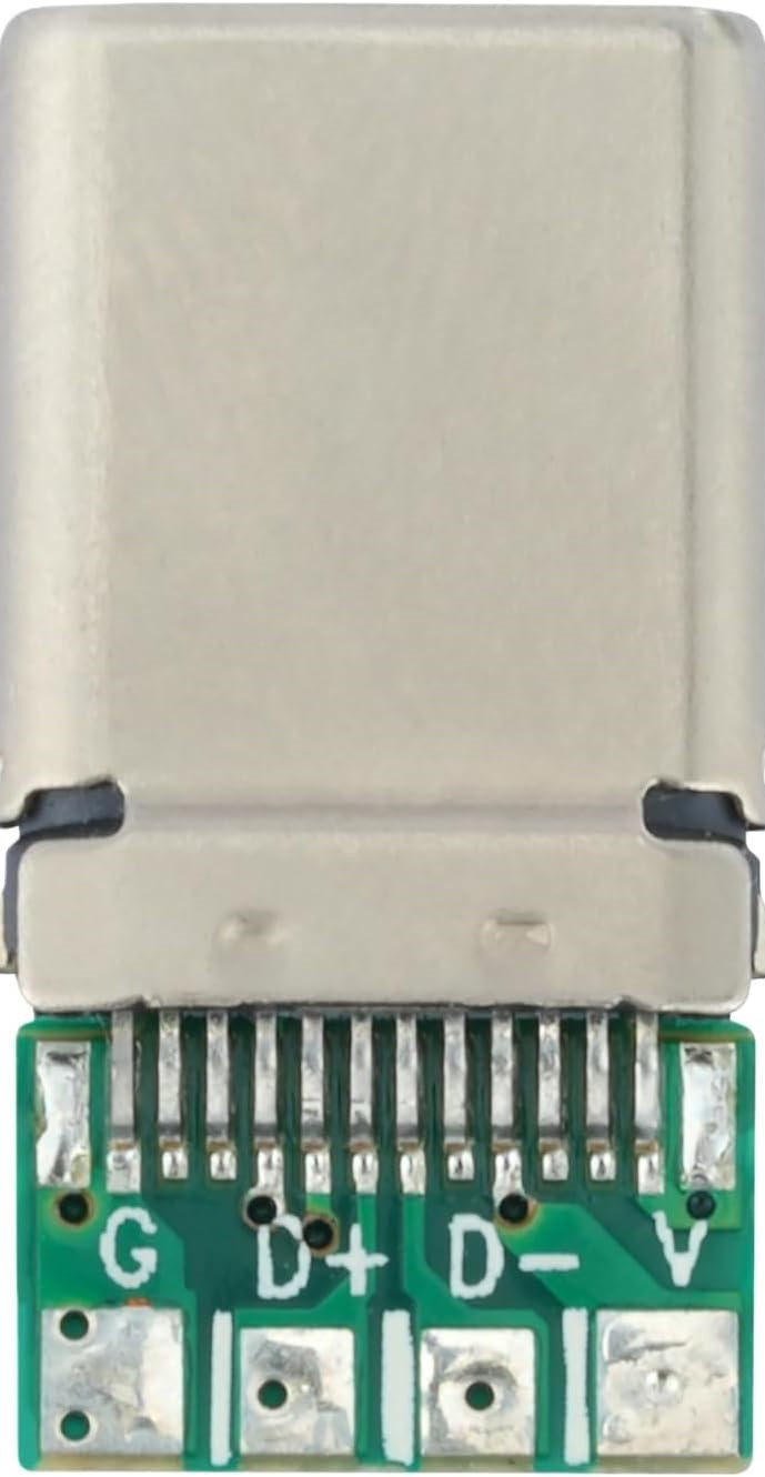
Pin Configuration and Descriptions
The USB Type-C connector has 24 pins, but not all are used in every USB C board. Below is a simplified pinout for a typical USB C board:
| Pin Name | Description | Notes |
|---|---|---|
| GND | Ground | Common ground for power and data |
| VBUS | Power input/output | Supplies 5V to 20V, depending on PD profile |
| D+ | USB 2.0 Data Positive | Used for USB 2.0 communication |
| D- | USB 2.0 Data Negative | Used for USB 2.0 communication |
| CC1, CC2 | Configuration Channel | Used for cable orientation and PD negotiation |
| TX+/TX- | USB 3.x Transmit Differential Pair | High-speed data transmission |
| RX+/RX- | USB 3.x Receive Differential Pair | High-speed data reception |
| SBU1, SBU2 | Sideband Use | Used for alternate modes like audio or video |
| Shield | Connector Shield | Provides EMI protection |
Note: Not all USB C boards support USB 3.x or power delivery. Check your specific board's datasheet for exact pin usage.
Usage Instructions
How to Use the USB C Board in a Circuit
- Power Delivery:
- Connect the VBUS and GND pins to your circuit's power input.
- If your board supports power delivery, ensure the connected device and cable are PD-compatible.
- Data Transfer:
- Use the D+ and D- pins for USB 2.0 communication.
- For USB 3.x, connect the TX+/TX- and RX+/RX- differential pairs.
- Video Output:
- If your board supports alternate modes (e.g., DisplayPort), connect the SBU1 and SBU2 pins as required by your display adapter.
- Prototyping:
- Use the USB C board as a power source or communication interface in your DIY projects. Ensure proper pin connections to avoid damage.
Important Considerations and Best Practices
- Cable Compatibility: Use high-quality USB Type-C cables to ensure reliable power delivery and data transfer.
- Voltage Regulation: If your circuit requires a specific voltage, use a voltage regulator to step down or step up the VBUS voltage.
- Overcurrent Protection: Add a fuse or current-limiting circuit to protect your components from overcurrent.
- Orientation Detection: The CC1 and CC2 pins help detect the cable orientation. Ensure your circuit accounts for this if needed.
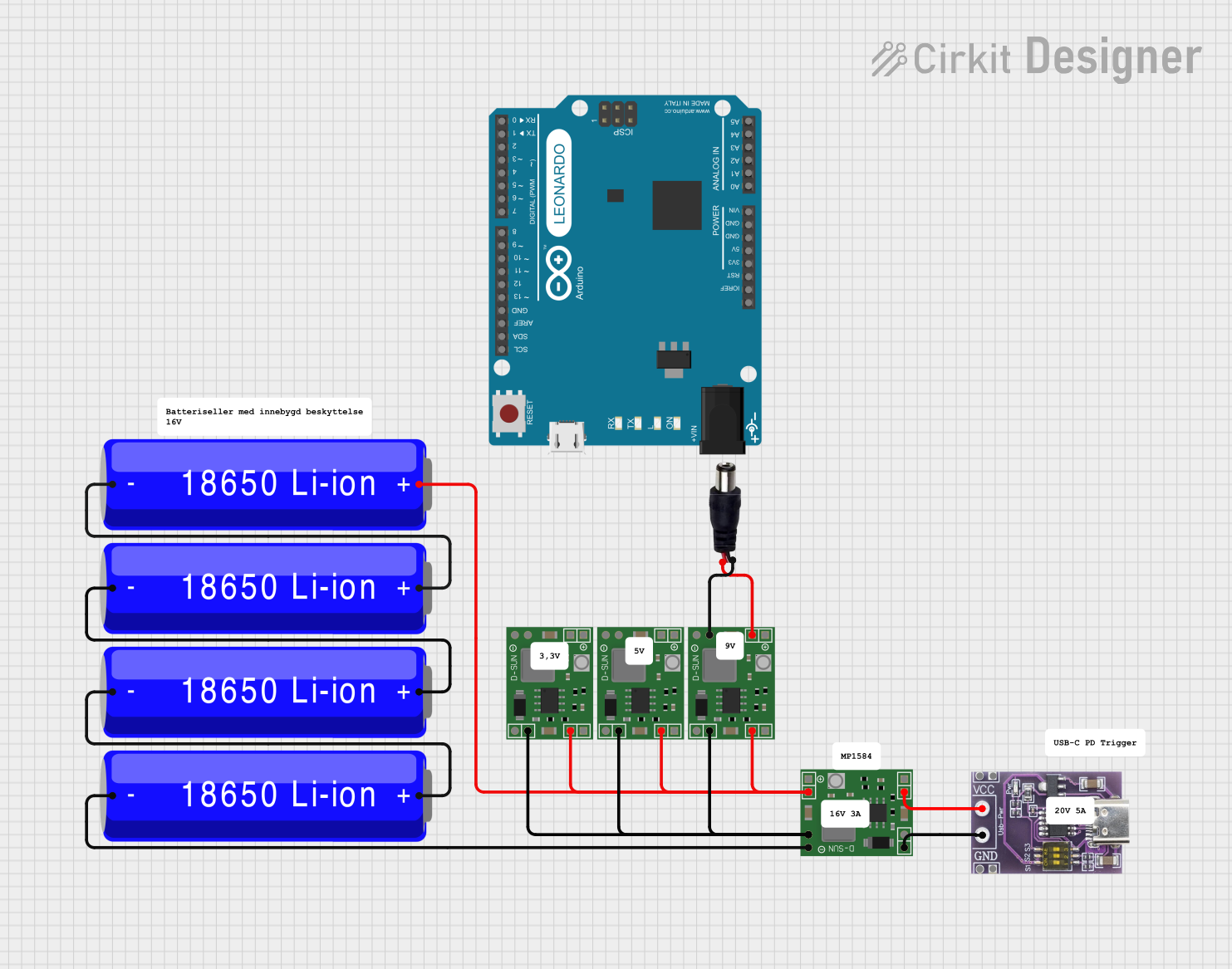
Example: Connecting to an Arduino UNO
To use a USB C board as a power source for an Arduino UNO, follow these steps:
- Connect the VBUS pin of the USB C board to the VIN pin of the Arduino UNO.
- Connect the GND pin of the USB C board to the GND pin of the Arduino UNO.
- Ensure the USB C power source provides a voltage between 7V and 12V for the Arduino's onboard regulator.
Here is an example Arduino sketch for reading data from a USB C-connected sensor:
// Example Arduino code for reading data from a USB C-connected sensor
// Ensure the sensor is properly connected to the USB C board's data pins

void setup() {
  Serial.begin(9600); // Initialize serial communication at 9600 baud
  while (!Serial) {
    ; // Wait for the serial port to connect (for native USB boards)
  }
  Serial.println("USB C Sensor Data Reader Initialized");
}

void loop() {
  if (Serial.available() > 0) {
    String data = Serial.readString(); // Read incoming data from the sensor
    Serial.print("Received Data: ");
    Serial.println(data); // Print the received data to the Serial Monitor
  }
}
Note: This example assumes the USB C board is connected to a sensor that communicates via serial data.
Troubleshooting and FAQs
Common Issues and Solutions
No Power Output:
- Cause: Incorrect cable or insufficient power source.
- Solution: Use a PD-compatible cable and ensure the power source meets the required voltage and current.
Data Transfer Fails:
- Cause: Incorrect pin connections or incompatible USB mode.
- Solution: Verify the connections for D+, D-, TX+/TX-, and RX+/RX-. Ensure the connected devices support the same USB version.
Overheating:
- Cause: Excessive current draw or poor heat dissipation.
- Solution: Check the current requirements of your circuit and add a heatsink if necessary.
Cable Orientation Not Detected:
- Cause: Missing or incorrect connection to CC1 and CC2 pins.
- Solution: Ensure proper wiring of the configuration channel pins.
FAQs
Q: Can I use a USB C board to charge my laptop?
- A: Yes, if the board supports power delivery and the power source provides sufficient voltage and current.
Q: Does every USB C board support video output?
- A: No, video output requires alternate mode support, which is not available on all USB C boards.
Q: How do I know if my USB C board supports USB 3.x?
- A: Check the board's datasheet or look for connections to the TX+/TX- and RX+/RX- pins.
Q: Can I use a USB C board with an older USB device?
- A: Yes, but you may need an adapter or cable that supports backward compatibility.