
Cirkit Designer
Your all-in-one circuit design IDE
Home /
Component Documentation
How to Use ESP32 CAM: Examples, Pinouts, and Specs
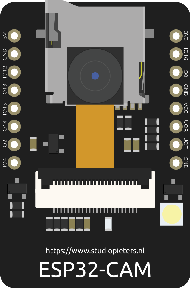
 Design with ESP32 CAM in Cirkit Designer
Introduction
The ESP32-CAM is a low-cost microcontroller with integrated Wi-Fi and Bluetooth capabilities, featuring a camera module for image capture and video streaming. It is widely used in IoT projects, surveillance systems, and smart home applications due to its compact size, powerful processing capabilities, and versatile connectivity options. The module is ideal for projects requiring wireless communication and real-time image or video processing.
Explore Projects Built with ESP32 CAM
ESP32 CAM Wi-Fi Controlled Camera with FTDI Programmer
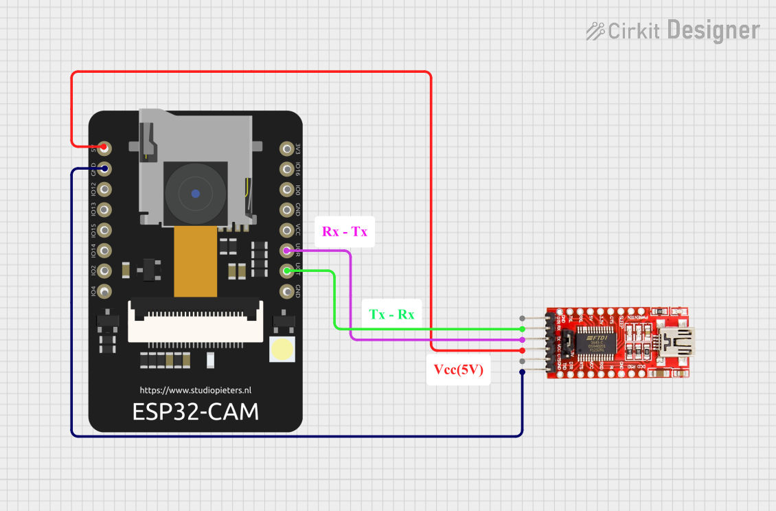
This circuit consists of an ESP32 CAM module connected to an FTDI Programmer for power and serial communication. The ESP32 CAM is programmed to capture images and stream them over WiFi, acting as a web server to provide live video feed.
Open Project in Cirkit DesignerESP32 CAM Wi-Fi Controlled Camera with FTDI Programmer
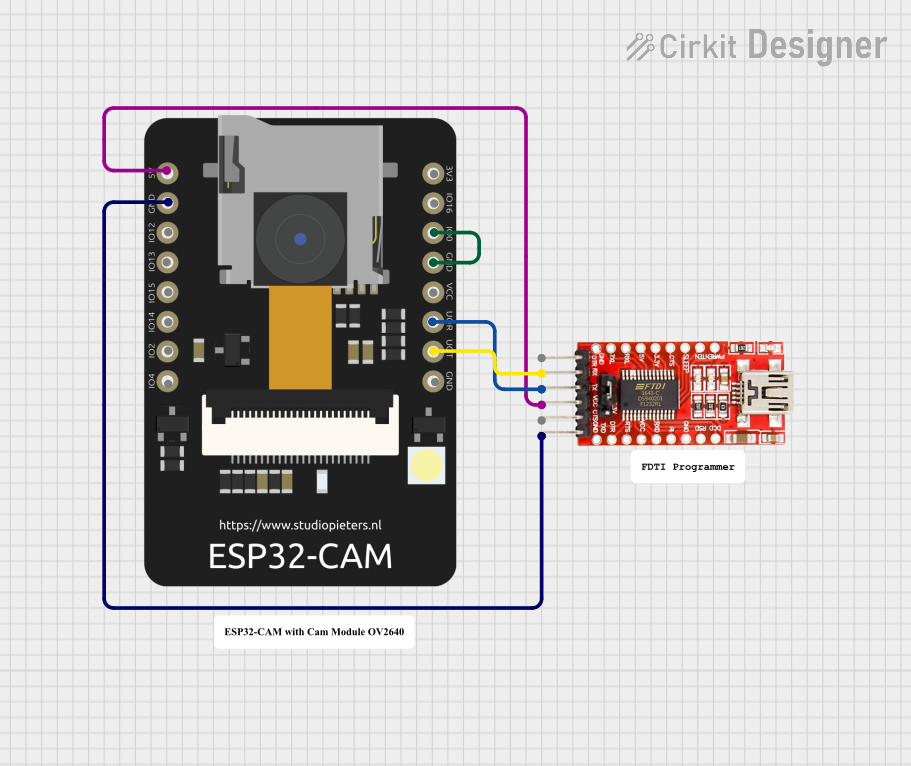
This circuit consists of an ESP32 CAM module connected to an FTDI Programmer for power and serial communication. The ESP32 CAM is programmed to capture images and stream them over WiFi, acting as a web server to provide a live video feed.
Open Project in Cirkit DesignerESP32 CAM Wi-Fi Controlled Live Video Streamer with FTDI Programmer
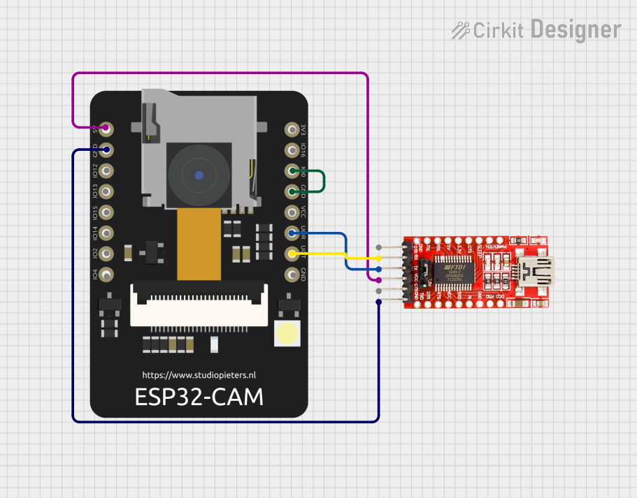
This circuit consists of an ESP32 CAM module connected to an FTDI Programmer for power and serial communication. The ESP32 CAM is programmed to capture images and stream them over WiFi, acting as a web server to provide a live video feed.
Open Project in Cirkit DesignerESP32 CAM Wi-Fi Controlled Camera with FTDI Programmer
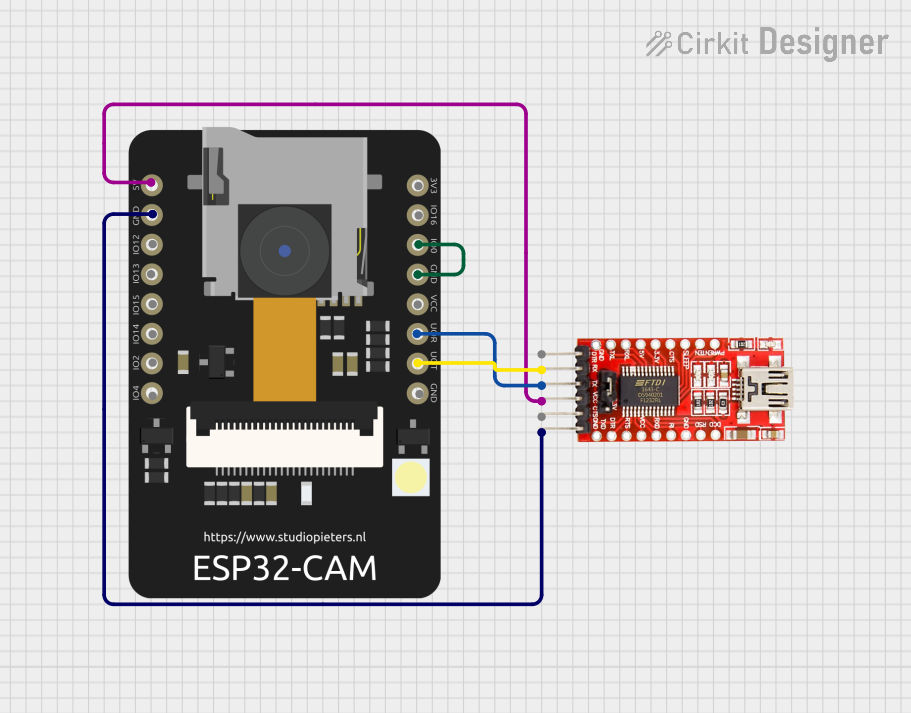
This circuit connects an ESP32 CAM module to an FTDI Programmer for power and serial communication. The ESP32 CAM is programmed to capture images and stream them over WiFi, acting as a web server to provide a live video feed.
Open Project in Cirkit DesignerExplore Projects Built with ESP32 CAM
ESP32 CAM Wi-Fi Controlled Camera with FTDI Programmer
This circuit consists of an ESP32 CAM module connected to an FTDI Programmer for power and serial communication. The ESP32 CAM is programmed to capture images and stream them over WiFi, acting as a web server to provide live video feed.
Open Project in Cirkit DesignerESP32 CAM Wi-Fi Controlled Camera with FTDI Programmer
This circuit consists of an ESP32 CAM module connected to an FTDI Programmer for power and serial communication. The ESP32 CAM is programmed to capture images and stream them over WiFi, acting as a web server to provide a live video feed.
Open Project in Cirkit DesignerESP32 CAM Wi-Fi Controlled Live Video Streamer with FTDI Programmer
This circuit consists of an ESP32 CAM module connected to an FTDI Programmer for power and serial communication. The ESP32 CAM is programmed to capture images and stream them over WiFi, acting as a web server to provide a live video feed.
Open Project in Cirkit DesignerESP32 CAM Wi-Fi Controlled Camera with FTDI Programmer
This circuit connects an ESP32 CAM module to an FTDI Programmer for power and serial communication. The ESP32 CAM is programmed to capture images and stream them over WiFi, acting as a web server to provide a live video feed.
Open Project in Cirkit DesignerCommon Applications
- IoT-based surveillance systems
- Smart home automation with video monitoring
- Face recognition and object detection
- Wireless image and video streaming
- Remote-controlled robots with live video feed
Technical Specifications
Key Technical Details
| Specification | Value |
|---|---|
| Microcontroller | ESP32-S (dual-core processor) |
| Wireless Connectivity | Wi-Fi 802.11 b/g/n, Bluetooth 4.2 |
| Camera Module | OV2640 (2MP resolution) |
| Flash Memory | 4 MB (PSRAM) |
| Operating Voltage | 3.3V |
| Input Voltage Range | 5V (via external power supply or USB) |
| GPIO Pins | 9 (configurable for various peripherals) |
| Interfaces | UART, SPI, I2C, PWM, ADC |
| Power Consumption | ~160 mA (active), ~10 µA (deep sleep) |
| Dimensions | 27mm x 40.5mm |
Pin Configuration and Descriptions
| Pin Name | Pin Number | Description |
|---|---|---|
| GND | 1 | Ground |
| 3.3V | 2 | 3.3V Power Supply Output |
| 5V | 3 | 5V Power Supply Input |
| GPIO0 | 4 | General Purpose I/O, used for boot mode |
| GPIO1 | 5 | UART TX (Serial Communication) |
| GPIO3 | 6 | UART RX (Serial Communication) |
| GPIO12 | 7 | General Purpose I/O |
| GPIO13 | 8 | General Purpose I/O |
| GPIO14 | 9 | General Purpose I/O |
| GPIO15 | 10 | General Purpose I/O |
| GPIO16 | 11 | General Purpose I/O |
| GPIO33 | 12 | General Purpose I/O |
| RESET | 13 | Reset Pin |
Usage Instructions
How to Use the ESP32-CAM in a Circuit
- Power Supply: Connect the 5V pin to a stable 5V power source. Ensure the ground (GND) is connected to the circuit's ground.
- Programming: Use an FTDI programmer or USB-to-serial adapter to upload code. Connect the following:
- FTDI TX to ESP32-CAM RX (GPIO3)
- FTDI RX to ESP32-CAM TX (GPIO1)
- GND to GND
- 5V to 5V
- GPIO0 to GND (for programming mode)
- Upload Code: Use the Arduino IDE or ESP-IDF to upload your program. Select the correct board (
AI-Thinker ESP32-CAM) and COM port. - Camera Initialization: Ensure the OV2640 camera module is securely connected to the ESP32-CAM board.
- Run the Program: After uploading, disconnect GPIO0 from GND and reset the board to run the program.
Important Considerations
- Power Supply: The ESP32-CAM requires a stable 5V power source. Insufficient power can cause boot failures or instability.
- Heat Management: The ESP32-CAM can get warm during operation. Ensure proper ventilation or use a heatsink if necessary.
- Antenna Placement: For optimal Wi-Fi performance, ensure the onboard antenna is not obstructed by metal or other materials.
- Boot Mode: Always connect GPIO0 to GND when uploading code. Disconnect it before running the program.
Example Code for Arduino IDE
Below is an example code to set up the ESP32-CAM as a Wi-Fi-based camera server:
#include <WiFi.h>
#include <esp_camera.h>

// Replace with your Wi-Fi credentials
const char* ssid = "Your_SSID";
const char* password = "Your_PASSWORD";

// Camera configuration
#define PWDN_GPIO_NUM    -1
#define RESET_GPIO_NUM   -1
#define XCLK_GPIO_NUM     0
#define SIOD_GPIO_NUM    26
#define SIOC_GPIO_NUM    27
#define Y9_GPIO_NUM      35
#define Y8_GPIO_NUM      34
#define Y7_GPIO_NUM      39
#define Y6_GPIO_NUM      36
#define Y5_GPIO_NUM      21
#define Y4_GPIO_NUM      19
#define Y3_GPIO_NUM      18
#define Y2_GPIO_NUM       5
#define VSYNC_GPIO_NUM   25
#define HREF_GPIO_NUM    23
#define PCLK_GPIO_NUM    22

void startCameraServer();

void setup() {
  Serial.begin(115200);
  Serial.println();

  // Connect to Wi-Fi
  WiFi.begin(ssid, password);
  while (WiFi.status() != WL_CONNECTED) {
    delay(500);
    Serial.print(".");
  }
  Serial.println("");
  Serial.println("WiFi connected");
  Serial.println("IP address: ");
  Serial.println(WiFi.localIP());

  // Camera configuration
  camera_config_t config;
  config.ledc_channel = LEDC_CHANNEL_0;
  config.ledc_timer = LEDC_TIMER_0;
  config.pin_d0 = Y2_GPIO_NUM;
  config.pin_d1 = Y3_GPIO_NUM;
  config.pin_d2 = Y4_GPIO_NUM;
  config.pin_d3 = Y5_GPIO_NUM;
  config.pin_d4 = Y6_GPIO_NUM;
  config.pin_d5 = Y7_GPIO_NUM;
  config.pin_d6 = Y8_GPIO_NUM;
  config.pin_d7 = Y9_GPIO_NUM;
  config.pin_xclk = XCLK_GPIO_NUM;
  config.pin_pclk = PCLK_GPIO_NUM;
  config.pin_vsync = VSYNC_GPIO_NUM;
  config.pin_href = HREF_GPIO_NUM;
  config.pin_sscb_sda = SIOD_GPIO_NUM;
  config.pin_sscb_scl = SIOC_GPIO_NUM;
  config.pin_pwdn = PWDN_GPIO_NUM;
  config.pin_reset = RESET_GPIO_NUM;
  config.xclk_freq_hz = 20000000;
  config.pixel_format = PIXFORMAT_JPEG;

  // Initialize the camera
  if (esp_camera_init(&config) != ESP_OK) {
    Serial.println("Camera init failed");
    return;
  }

  // Start the camera server
  startCameraServer();
  Serial.println("Camera ready! Use the IP address to view the stream.");
}

void loop() {
  delay(10000); // Keep the program running
}
Troubleshooting and FAQs
Common Issues
- Boot Failure: The ESP32-CAM may fail to boot if the power supply is insufficient. Use a stable 5V source with at least 1A current.
- Camera Initialization Error: Ensure the OV2640 camera module is securely connected. Check for loose connections or damaged cables.
- Wi-Fi Connection Issues: Double-check the SSID and password. Ensure the router is within range and supports 2.4 GHz Wi-Fi.
- Code Upload Failure: Verify that GPIO0 is connected to GND during programming. Ensure the correct COM port and board are selected in the Arduino IDE.
Solutions and Tips
- Use a dedicated power supply instead of relying on the FTDI programmer for power.
- If the ESP32-CAM gets too hot, consider adding a small heatsink or improving ventilation.
- For debugging, use the Serial Monitor in the Arduino IDE to view error messages and logs.
- If the camera stream is slow, reduce the resolution or frame rate in the code.
By following this documentation, you can effectively use the ESP32-CAM in your projects and troubleshoot common issues with ease.