How to Use BLDC Motor: Examples, Pinouts, and Specs
Introduction
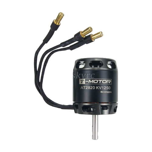
The T-motor AS2820 is a high-performance Brushless DC Motor (BLDC) designed for a variety of applications that require high efficiency, reliability, and longevity. Unlike traditional brushed motors, the AS2820 operates using electronic commutation, which extends the life of the motor by eliminating the wear and tear associated with mechanical brushes. This motor is commonly used in applications such as drones, electric vehicles, industrial automation, and robotics.
Explore Projects Built with BLDC Motor
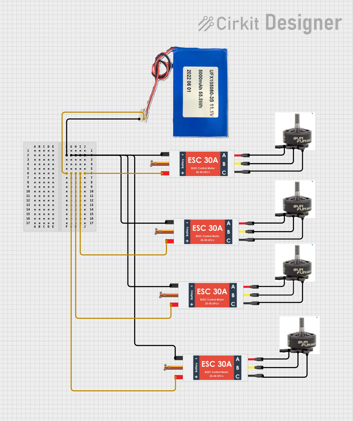

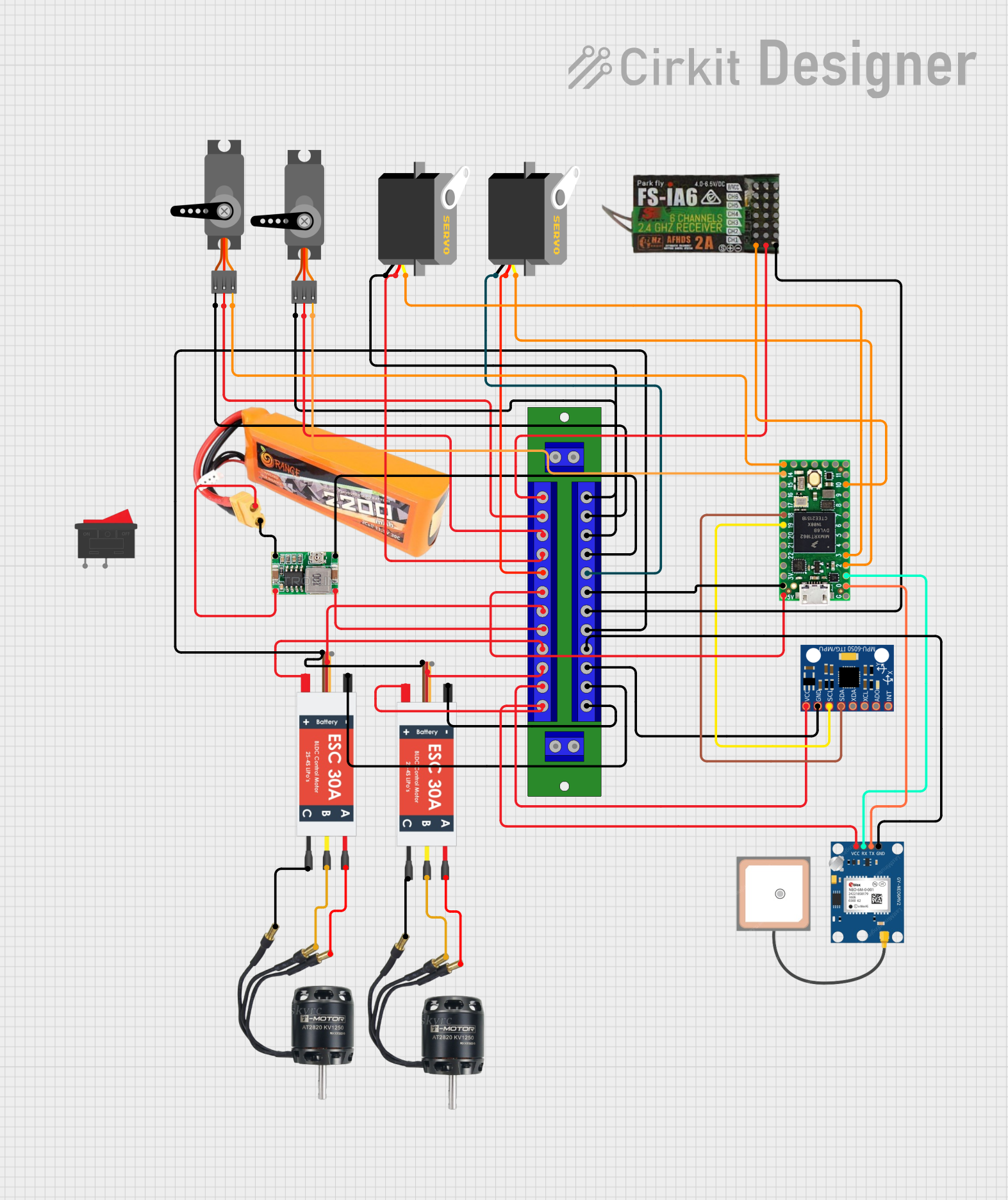
Explore Projects Built with BLDC Motor
Technical Specifications
General Characteristics
- Manufacturer: T-motor
- Part ID: AS2820
- Motor Type: Brushless DC (BLDC)
- Rated Voltage: 22.2V
- Max Current: 45A
- Continuous Power: 800W
- Peak Power: 1800W
- Efficiency: Up to 90%
- Number of Poles: 14
- KV Rating: 920 RPM/V
- Shaft Diameter: 4mm
- Motor Diameter: 28mm
- Motor Length: 20mm
- Weight: 70g
Pin Configuration and Descriptions
| Pin Number | Description | Notes |
|---|---|---|
| 1 | Phase A Output | Connect to ESC Phase A |
| 2 | Phase B Output | Connect to ESC Phase B |
| 3 | Phase C Output | Connect to ESC Phase C |
| 4 | Hall Sensor Vcc | Supply voltage for Hall sensors |
| 5 | Hall Sensor GND | Ground for Hall sensors |
| 6 | Hall Sensor Output A | Hall sensor A signal |
| 7 | Hall Sensor Output B | Hall sensor B signal |
| 8 | Hall Sensor Output C | Hall sensor C signal |
Usage Instructions
Connecting to a Circuit
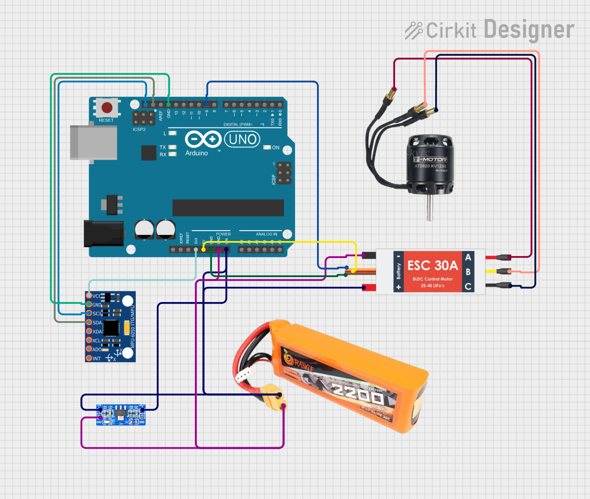
Electronic Speed Controller (ESC): The AS2820 must be connected to an appropriate ESC that can handle the motor's voltage and current requirements. The ESC will provide the necessary electronic commutation.
Power Supply: Ensure that the power supply can deliver the required voltage and current without sagging or voltage drop under load.
Wiring: Use thick enough wires to handle the current without excessive heat buildup. The wire gauge should be chosen based on the maximum current rating of the motor.
Mounting: Secure the motor firmly to the application frame to prevent vibrations and potential damage.
Best Practices
- ESC Calibration: Calibrate the ESC according to the manufacturer's instructions to ensure proper motor operation.
- Propeller Balancing: If used in a drone, balance the propellers to reduce vibrations and increase motor lifespan.
- Cooling: Ensure adequate airflow around the motor to prevent overheating during operation.
- Inspection: Regularly inspect the motor for any signs of wear or damage, especially after incidents or crashes.
Troubleshooting and FAQs
Common Issues
- Motor not spinning: Check connections, ensure the ESC is properly calibrated, and verify that the power supply is adequate.
- Overheating: Ensure proper cooling, check for obstructions, and verify that the motor is not overloaded.
- Vibrations: Check for unbalanced propellers or loose mounting.
FAQs
Q: Can I run the motor at a higher voltage than rated?
- A: Exceeding the rated voltage can damage the motor and ESC. Always adhere to the manufacturer's specifications.
Q: How do I reverse the motor direction?
- A: Swap any two of the three-phase wires between the motor and ESC to reverse the direction.
Q: What is the lifespan of the AS2820 motor?
- A: The lifespan depends on the usage conditions, but BLDC motors generally have a longer lifespan than brushed motors due to the lack of mechanical brushes.
Example Arduino UNO Code
Below is an example code snippet for controlling a BLDC motor like the AS2820 using an Arduino UNO and an ESC. This example assumes the use of a standard servo library for ESC control.
#include <Servo.h>

Servo esc; // Create a servo object to control the ESC

void setup() {
  esc.attach(9); // Attach the ESC signal cable to pin 9
  esc.writeMicroseconds(1000); // Send the minimum signal to the ESC
  delay(1000); // Wait 1 second for the ESC to initialize
}

void loop() {
  int throttle = 1500; // Set the throttle (1000 = off, 2000 = full speed)
  esc.writeMicroseconds(throttle); // Send the throttle signal to the ESC
  delay(15); // Wait for a short period before the next update
}
Note: Before using this code, ensure that the ESC is properly calibrated to recognize the minimum and maximum pulse widths (usually 1000µs for minimum and 2000µs for maximum throttle).
Remember to follow the ESC's manual for specific instructions on calibration and safety measures. The above code is a basic example and may require adjustments based on your specific ESC and application requirements.