How to Use ESP32-CAM: Examples, Pinouts, and Specs

Introduction
The ESP32-CAM is a low-cost development board manufactured by Ai Thinker. It features a built-in camera module and Wi-Fi capabilities, making it ideal for IoT applications that require video streaming, image capture, or remote monitoring. The board is based on the powerful ESP32 chip, which integrates Wi-Fi and Bluetooth functionality, along with a dual-core processor.
Explore Projects Built with ESP32-CAM


Explore Projects Built with ESP32-CAM
Common Applications and Use Cases
- Wireless video surveillance systems
- Smart home devices (e.g., doorbell cameras, baby monitors)
- IoT projects requiring image recognition or video streaming
- Remote-controlled robots with live video feeds
- Face detection and recognition systems
Technical Specifications
The ESP32-CAM is a compact and versatile module with the following key specifications:
| Parameter | Value |
|---|---|
| Microcontroller | ESP32-D0WDQ6 (dual-core processor) |
| Camera Module | OV2640 (2MP resolution) |
| Flash Memory | 4 MB (PSRAM: 8 MB) |
| Wi-Fi | 802.11 b/g/n |
| Bluetooth | BLE and Bluetooth 4.2 |
| Operating Voltage | 3.3V |
| Input Voltage Range | 5V (via external power supply or USB-to-TTL module) |
| GPIO Pins | 9 GPIO pins available for user applications |
| Interfaces | UART, SPI, I2C, PWM, ADC |
| Dimensions | 27mm x 40.5mm |
| Power Consumption | Deep Sleep: ~6mA, Active Mode: ~160mA |
| Camera Features | Support for JPEG, BMP, and grayscale image formats |
| Operating Temperature | -20°C to 85°C |
Pin Configuration and Descriptions
The ESP32-CAM has a total of 16 pins. Below is the pinout and description:
| Pin Name | Pin Number | Description |
|---|---|---|
| GND | 1 | Ground connection |
| 3.3V | 2 | 3.3V power supply output |
| 5V | 3 | 5V power supply input |
| U0R | 4 | UART0 RX pin (used for programming and debugging) |
| U0T | 5 | UART0 TX pin (used for programming and debugging) |
| GPIO0 | 6 | GPIO pin 0 (used for boot mode selection) |
| GPIO1 | 7 | GPIO pin 1 (used for general-purpose I/O) |
| GPIO2 | 8 | GPIO pin 2 (used for LED flash control) |
| GPIO3 | 9 | GPIO pin 3 (used for general-purpose I/O) |
| GPIO4 | 10 | GPIO pin 4 (used for general-purpose I/O) |
| GPIO12 | 11 | GPIO pin 12 (used for SD card data line) |
| GPIO13 | 12 | GPIO pin 13 (used for SD card data line) |
| GPIO14 | 13 | GPIO pin 14 (used for SD card clock line) |
| GPIO15 | 14 | GPIO pin 15 (used for SD card command line) |
| GPIO16 | 15 | GPIO pin 16 (used for general-purpose I/O) |
| RESET | 16 | Reset pin (active low) |
Usage Instructions
How to Use the ESP32-CAM in a Circuit
- Power Supply: Provide a stable 5V power supply to the ESP32-CAM via the 5V pin. Avoid powering the board directly from the 3.3V pin unless you have a regulated 3.3V source.
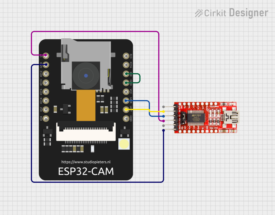
- Programming: Use a USB-to-TTL converter (e.g., FTDI module) to program the ESP32-CAM. Connect the following:
- TX of the USB-to-TTL module to U0R (RX) of the ESP32-CAM.
- RX of the USB-to-TTL module to U0T (TX) of the ESP32-CAM.
- GND of the USB-to-TTL module to GND of the ESP32-CAM.
- 5V of the USB-to-TTL module to the 5V pin of the ESP32-CAM.
- Boot Mode: To upload code, connect GPIO0 to GND and press the RESET button. After uploading, disconnect GPIO0 from GND and reset the board.
- Camera Setup: Ensure the OV2640 camera module is securely connected to the ESP32-CAM's camera connector.
Important Considerations and Best Practices
- Power Supply: The ESP32-CAM requires a stable 5V power source. Insufficient power can cause the board to reset or fail to boot.
- Heat Management: The ESP32-CAM can get warm during operation. Ensure proper ventilation or use a heatsink if necessary.
- Antenna: For better Wi-Fi performance, use an external antenna if the onboard antenna is insufficient for your application.
- SD Card: If using an SD card, format it as FAT32 and ensure it is properly inserted into the slot.
Example Code for Arduino UNO
Below is an example of how to use the ESP32-CAM with the Arduino IDE to capture and stream video:
#include <WiFi.h>
#include <esp_camera.h>

// Replace with your Wi-Fi credentials
const char* ssid = "Your_SSID";
const char* password = "Your_PASSWORD";

void startCameraServer();

void setup() {
  Serial.begin(115200);

  // Connect to Wi-Fi
  WiFi.begin(ssid, password);
  while (WiFi.status() != WL_CONNECTED) {
    delay(500);
    Serial.print(".");
  }
  Serial.println("");
  Serial.println("WiFi connected");
  Serial.println("IP address: ");
  Serial.println(WiFi.localIP());

  // Initialize the camera
  camera_config_t config;
  config.ledc_channel = LEDC_CHANNEL_0;
  config.ledc_timer = LEDC_TIMER_0;
  config.pin_d0 = 5;
  config.pin_d1 = 18;
  config.pin_d2 = 19;
  config.pin_d3 = 21;
  config.pin_d4 = 36;
  config.pin_d5 = 39;
  config.pin_d6 = 34;
  config.pin_d7 = 35;
  config.pin_xclk = 0;
  config.pin_pclk = 22;
  config.pin_vsync = 25;
  config.pin_href = 23;
  config.pin_sscb_sda = 26;
  config.pin_sscb_scl = 27;
  config.pin_pwdn = -1;
  config.pin_reset = -1;
  config.xclk_freq_hz = 20000000;
  config.pixel_format = PIXFORMAT_JPEG;

  // Initialize the camera
  if (esp_camera_init(&config) != ESP_OK) {
    Serial.println("Camera init failed");
    return;
  }

  // Start the camera server
  startCameraServer();
}

void loop() {
  // Main loop does nothing; the camera server handles everything
}
Troubleshooting and FAQs
Common Issues and Solutions
ESP32-CAM Not Booting:
- Ensure the power supply is stable and provides sufficient current (at least 500mA).
- Check that GPIO0 is connected to GND during programming.
Camera Initialization Failed:
- Verify that the OV2640 camera module is properly connected.
- Ensure the camera configuration in the code matches the hardware.
Wi-Fi Connection Issues:
- Double-check the SSID and password in your code.
- Ensure the ESP32-CAM is within range of the Wi-Fi router.
Overheating:
- Provide adequate ventilation or use a heatsink to dissipate heat.
FAQs
Can I use the ESP32-CAM without an external antenna? Yes, the onboard antenna is sufficient for most applications, but an external antenna can improve range.
What is the maximum resolution of the camera? The OV2640 camera supports up to 1600x1200 (UXGA) resolution.
Can I use the ESP32-CAM with a battery? Yes, you can use a 3.7V LiPo battery with a step-up converter to provide 5V input.
Does the ESP32-CAM support deep sleep mode? Yes, the ESP32-CAM supports deep sleep mode to conserve power.