How to Use DC Mini Metal Gear Motor: Examples, Pinouts, and Specs

Introduction
The DC Mini Metal Gear Motor is a compact and robust electric motor designed for precision movement in a variety of applications. Its integrated metal gears provide high torque and durability, making it suitable for small-scale robotics, automation projects, and hobbyist applications where precise motion control is required.
Explore Projects Built with DC Mini Metal Gear Motor
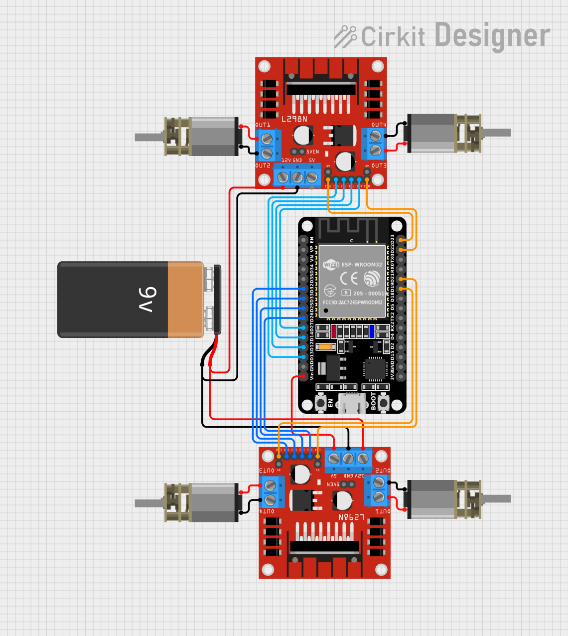

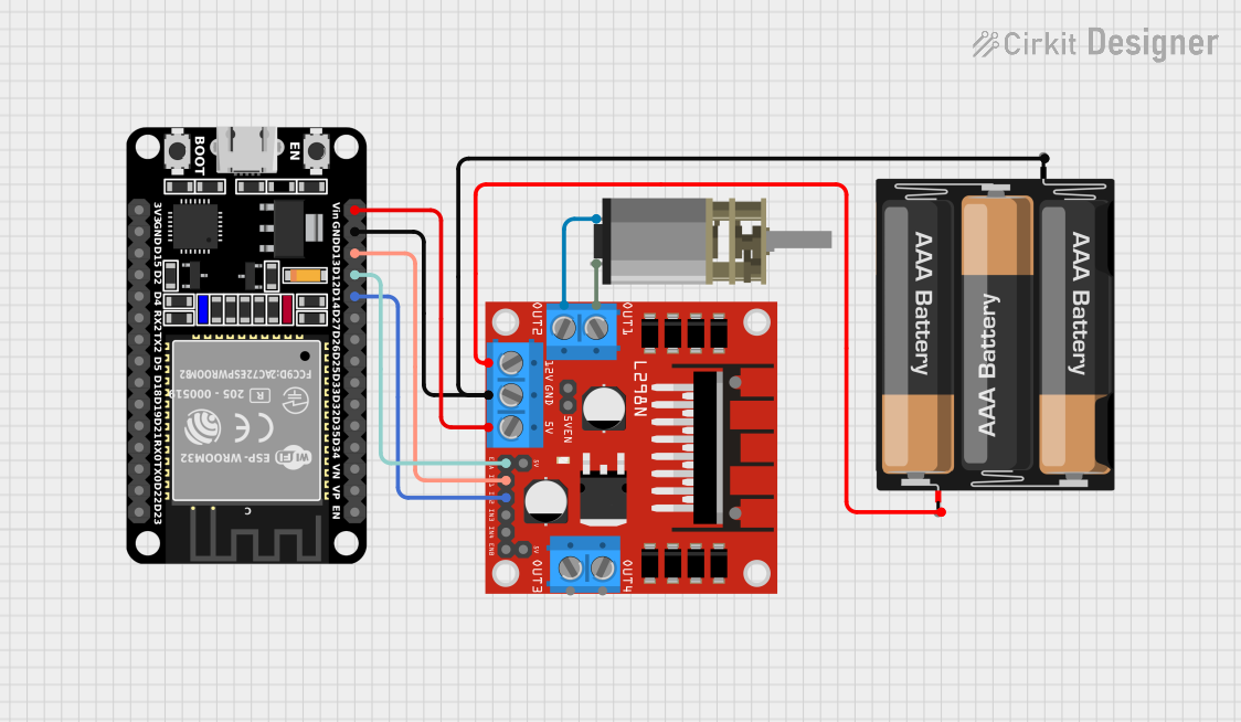
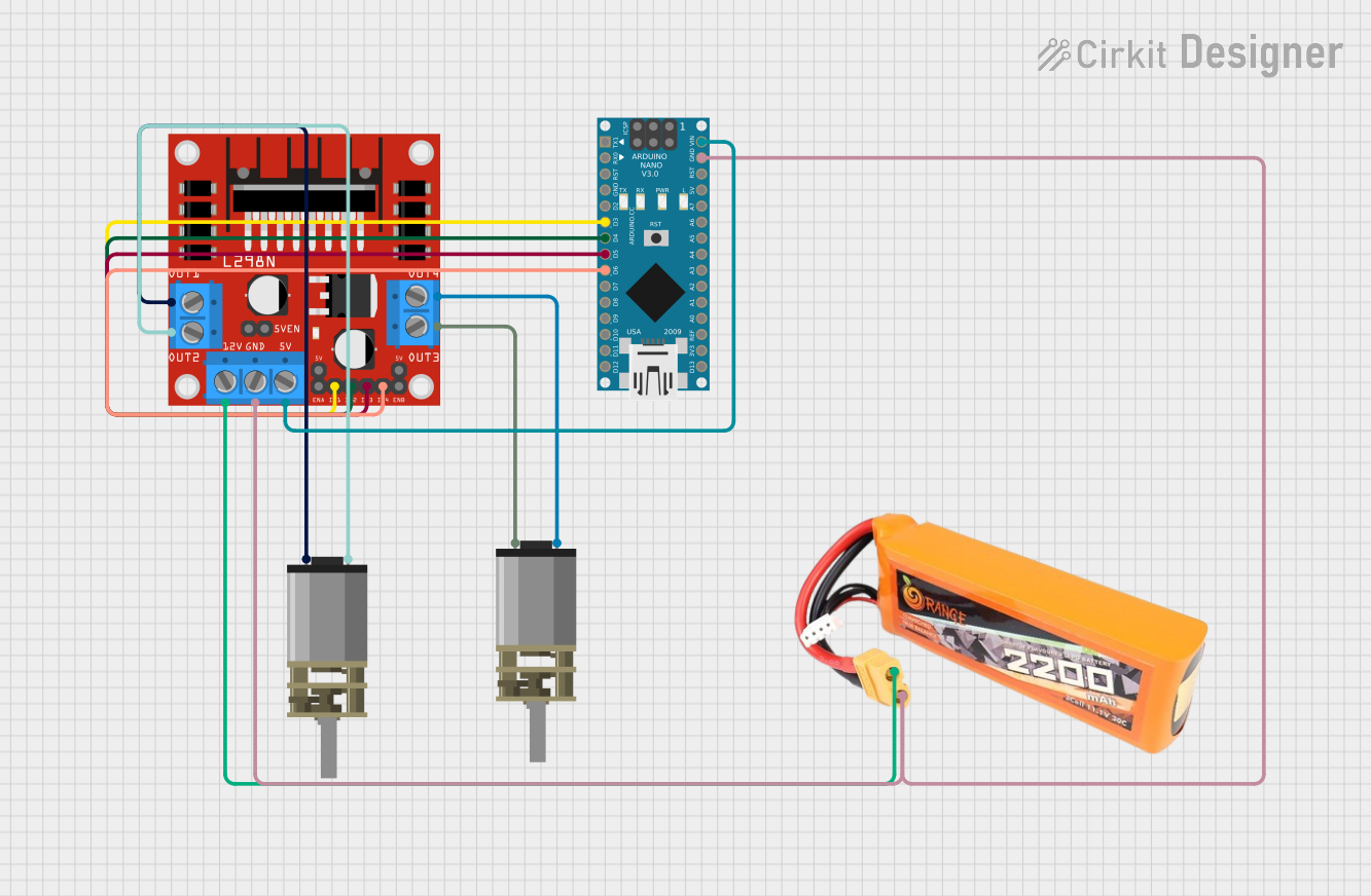
Explore Projects Built with DC Mini Metal Gear Motor
Common Applications and Use Cases
- Robotics: Actuating wheels, joints, and manipulators.
- Hobby Projects: Model vehicles, animatronics, and custom toys.
- Automation: Small-scale conveyor systems, sorting machines.
- Educational: Teaching principles of mechanics and electronics.
Technical Specifications
Key Technical Details
- Voltage Range: Typically 3V to 12V DC
- No-Load Speed: Varies by model (e.g., 100 RPM at 6V)
- Stall Torque: Varies by model (e.g., 2 kg-cm at 6V)
- Gear Ratio: Varies by model (e.g., 1:150)
- Operating Temperature: -10°C to +60°C
Pin Configuration and Descriptions
| Pin Number | Description | Notes |
|---|---|---|
| 1 | Motor + (Vcc) | Connect to positive voltage |
| 2 | Motor - (GND) | Connect to ground |
Usage Instructions
How to Use the Component in a Circuit
- Power Supply: Connect the motor's positive and negative terminals to your power supply, ensuring that the voltage is within the motor's specified range.
- Control: To control the motor's direction and speed, use a motor driver or an H-bridge circuit connected to a microcontroller like an Arduino UNO.
- Mounting: Secure the motor to your project using the mounting holes provided on the motor's casing.
Important Considerations and Best Practices
- Current Draw: Ensure your power supply can handle the motor's maximum current draw, especially during startup or under load.
- Voltage: Applying a voltage higher than the motor's rated maximum can result in overheating and damage.
- Load: Avoid placing excessive loads on the motor's shaft, which can strain the gears and motor.
- Heat Dissipation: Allow for adequate ventilation around the motor to prevent overheating.
Example Code for Arduino UNO
#include <Arduino.h>

// Define motor control pins
const int motorPin1 = 3; // H-bridge leg 1 (pin 2, 1A)
const int motorPin2 = 4; // H-bridge leg 2 (pin 7, 2A)

void setup() {
  // Set motor control pins as outputs
  pinMode(motorPin1, OUTPUT);
  pinMode(motorPin2, OUTPUT);
}

void loop() {
  // Spin motor clockwise
  digitalWrite(motorPin1, HIGH);
  digitalWrite(motorPin2, LOW);
  delay(1000); // Run for 1 second

  // Stop motor
  digitalWrite(motorPin1, LOW);
  digitalWrite(motorPin2, LOW);
  delay(1000); // Stop for 1 second

  // Spin motor counterclockwise
  digitalWrite(motorPin1, LOW);
  digitalWrite(motorPin2, HIGH);
  delay(1000); // Run for 1 second

  // Stop motor
  digitalWrite(motorPin1, LOW);
  digitalWrite(motorPin2, LOW);
  delay(1000); // Stop for 1 second
}
Troubleshooting and FAQs
Common Issues
- Motor not spinning: Check power supply and connections. Ensure the voltage is within the specified range.
- Low torque or slow speed: Verify that the motor is not overloaded and the power supply can handle the current draw.
- Overheating: Ensure proper ventilation and that the motor is not being overdriven.
Solutions and Tips for Troubleshooting
- Check Connections: Loose or incorrect wiring can cause functionality issues.
- Test Power Supply: Use a multimeter to ensure the power supply is delivering the correct voltage.
- Load Testing: Reduce the load on the motor to see if performance improves.
FAQs
Q: Can I reverse the motor's direction? A: Yes, by reversing the polarity of the motor's power supply or using an H-bridge.
Q: What is the lifespan of the gears? A: The lifespan depends on the load and usage frequency. Under normal conditions, the gears are designed to last for the motor's operational life.
Q: Can I control the speed of the motor? A: Yes, speed control can be achieved using pulse-width modulation (PWM) through a motor driver connected to a microcontroller.