How to Use Adafruit AP3429 3.3V Buck: Examples, Pinouts, and Specs
Introduction
The Adafruit AP3429 3.3V Buck Converter is a compact, high-efficiency voltage regulator designed to provide a stable 3.3V output from a higher input voltage source. This component is ideal for powering a wide range of digital circuits, microcontrollers, and sensors that require a regulated 3.3V supply. Its small form factor and ease of use make it suitable for portable devices, IoT applications, and embedded systems.
Explore Projects Built with Adafruit AP3429 3.3V Buck


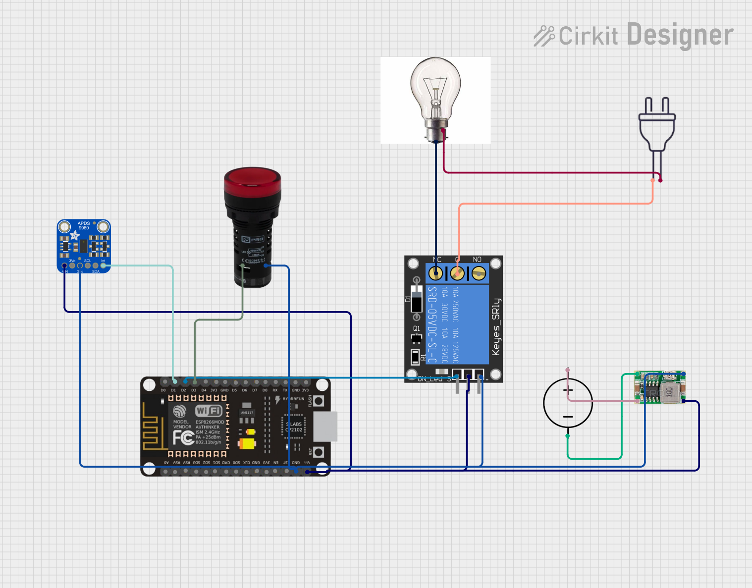
Explore Projects Built with Adafruit AP3429 3.3V Buck
Technical Specifications
Key Technical Details
- Input Voltage Range: 4.5V to 16V
- Output Voltage: 3.3V
- Maximum Output Current: 2A
- Efficiency: Up to 95%
- Switching Frequency: 1.4MHz
- Operating Temperature Range: -40°C to 85°C
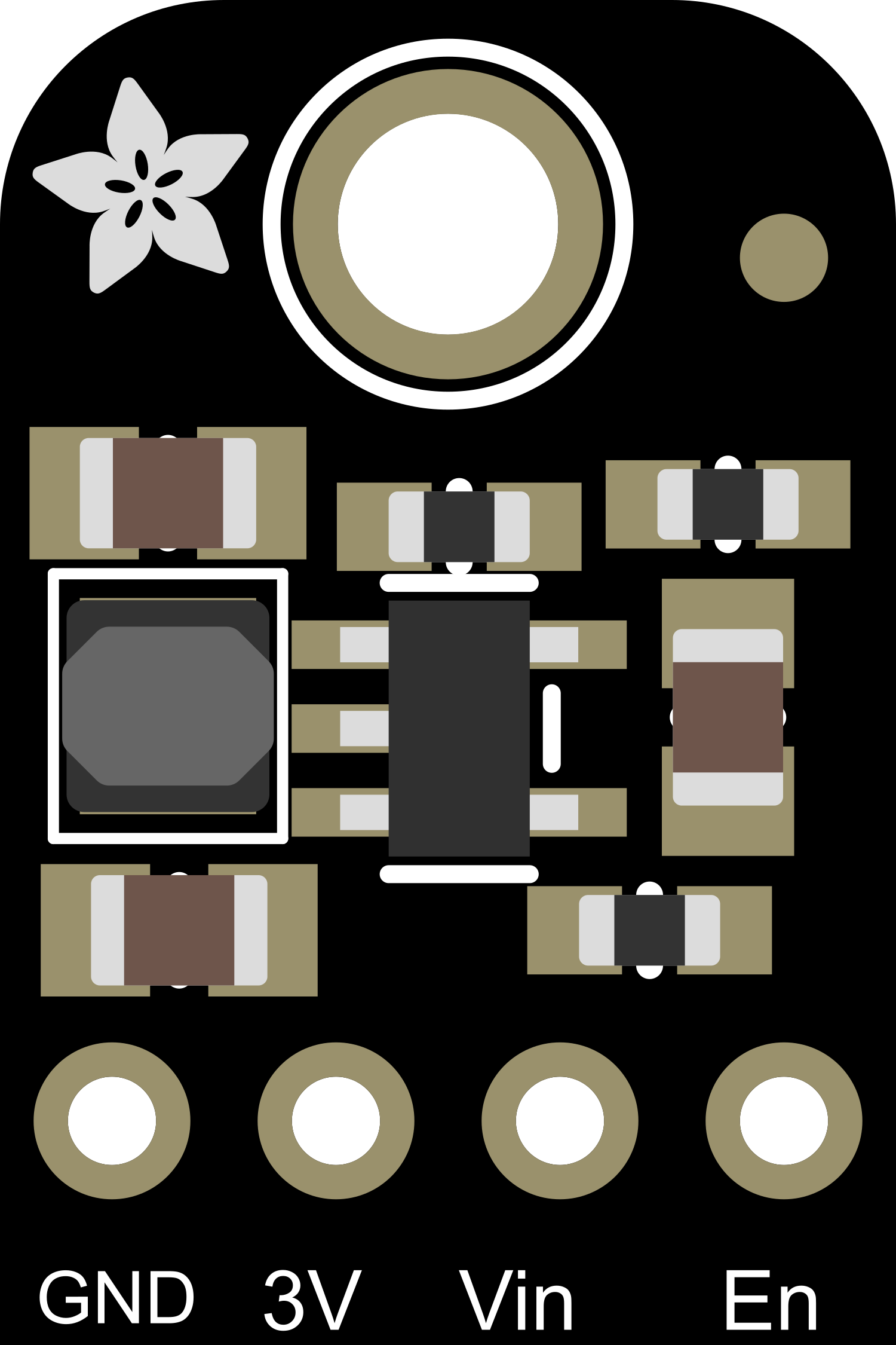
Pin Configuration and Descriptions
| Pin Number | Name | Description |
|---|---|---|
| 1 | VIN | Input voltage (4.5V to 16V) |
| 2 | GND | Ground connection |
| 3 | VOUT | Regulated 3.3V output |
| 4 | EN | Enable pin (active high) |
Usage Instructions
Integration into a Circuit
Power Connections:
- Connect the VIN pin to your input voltage source (4.5V to 16V).
- Connect the GND pin to the common ground of your system.
- The VOUT pin will provide the regulated 3.3V output.
Enabling the Converter:
- The EN pin can be left unconnected if you want the converter to be always on.
- To control the power state, connect the EN pin to a digital output of a microcontroller or a switch. Apply a high level to enable the converter.
Capacitor Recommendations:
- It is recommended to place a 10μF or greater capacitor close to the input and output pins to stabilize the voltage and reduce noise.
Best Practices
- Ensure that the input voltage is within the specified range to prevent damage.
- Do not exceed the maximum output current of 2A.
- Provide adequate cooling if the converter is operating at high loads for extended periods.
- Keep the converter away from high-temperature sources to maintain optimal efficiency.
Troubleshooting and FAQs
Common Issues
Output Voltage is Unstable or Incorrect:
- Check if the input voltage is within the specified range.
- Ensure that the capacitors are correctly placed and have adequate capacitance.
- Verify that the load does not exceed the maximum current rating.
Converter Does Not Power On:
- Confirm that the EN pin is either connected to a high signal or left unconnected.
- Check for any short circuits or incorrect wiring.
FAQs
Q: Can I adjust the output voltage of the AP3429? A: No, the output voltage is fixed at 3.3V.
Q: What is the purpose of the EN pin? A: The EN pin allows you to turn the converter on or off using an external control signal.
Q: Is it necessary to use capacitors with the AP3429? A: While the AP3429 may work without capacitors, it is strongly recommended to use them for stable operation and to minimize voltage ripple.
Example Arduino UNO Connection and Code
The following example demonstrates how to connect the Adafruit AP3429 3.3V Buck Converter to an Arduino UNO and control the enable pin.
Circuit Connection
- VIN to a 5V to 16V power source
- GND to Arduino GND
- VOUT to the VCC of a 3.3V device (e.g., sensor)
- EN to Arduino digital pin 2
Arduino Code
const int enablePin = 2; // Connect the EN pin to digital pin 2

void setup() {
  pinMode(enablePin, OUTPUT); // Set the enable pin as an output
  digitalWrite(enablePin, HIGH); // Enable the AP3429
}

void loop() {
  // Your code to interact with the 3.3V device
  // Use digitalWrite(enablePin, LOW) to disable the AP3429
}
Remember to include comments within the 80 character line limit and wrap them as needed. This code snippet simply enables the AP3429, allowing the connected 3.3V device to operate. You can toggle the enable pin to control power to the device programmatically.