How to Use copper coil: Examples, Pinouts, and Specs
Introduction
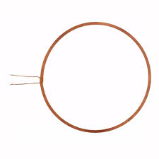
A copper coil, also known as an inductor, is a passive electronic component consisting of a wire wound around a core, which can be air or a magnetic material. Copper coils are widely used in electronic circuits for various applications such as filtering, energy storage, and in transformers for voltage conversion.
Explore Projects Built with copper coil

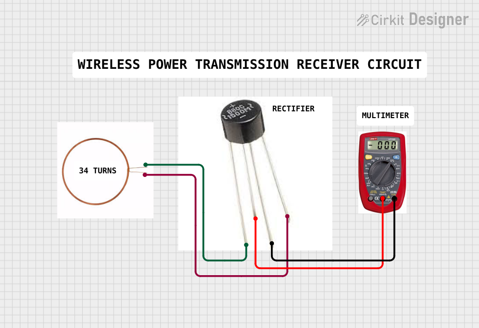

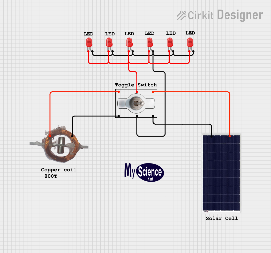
Explore Projects Built with copper coil
Common Applications and Use Cases
- LC Filters: In radio frequency (RF) circuits to filter specific frequencies.
- Transformers: In power supplies to step up or step down voltage levels.
- Electromagnets: In relays and solenoids for creating magnetic fields.
- Energy Storage: In power electronics to store energy in the magnetic field during one part of a cycle and release it in another.
Technical Specifications
Key Technical Details
- Inductance (L): The inductance value, typically measured in henries (H), millihenries (mH), or microhenries (µH).
- Current Rating (I): The maximum current the coil can carry before saturation or overheating, measured in amperes (A).
- DC Resistance (DCR): The resistance of the wire, measured in ohms (Ω).
- Quality Factor (Q): A dimensionless parameter that describes the efficiency of the coil at a specified frequency.
- Self-Resonant Frequency (SRF): The frequency at which the coil's inductance cancels out its parasitic capacitance, measured in hertz (Hz).
Pin Configuration and Descriptions
Since a copper coil is a two-terminal component, it does not have a complex pin configuration. The two terminals are simply the ends of the copper wire. Below is a table describing the terminals:
| Terminal | Description |
|---|---|
| 1 | Start of the copper winding |
| 2 | End of the copper winding |
Usage Instructions
How to Use the Component in a Circuit
- Identify the Inductance Value: Check the inductance value of the coil, which is usually specified in the datasheet.
- Connect to the Circuit: Solder or connect the coil's terminals to the circuit, ensuring proper orientation if the coil has a polarity due to a magnetic core.
- Observe Current Ratings: Ensure the current flowing through the coil does not exceed its current rating.
Important Considerations and Best Practices
- Avoid Saturation: Keep the current through the coil below the saturation current to prevent inductance value degradation.
- Heat Dissipation: Ensure adequate spacing around the coil for heat dissipation.
- Parasitic Capacitance: Be aware of the parasitic capacitance, which can affect high-frequency performance.
- Mounting: Secure the coil to prevent movement, which could lead to microphonics or physical damage.
Troubleshooting and FAQs
Common Issues Users Might Face
- Overheating: Caused by excessive current or poor heat dissipation.
- Noise: Due to improper filtering or shielding.
- Physical Damage: From dropping or mishandling the coil.
Solutions and Tips for Troubleshooting
- Check Current: Ensure the current is within the specified limit.
- Improve Cooling: Increase airflow or add a heat sink if necessary.
- Inspect for Damage: Look for physical signs of damage or loose connections.
FAQs
Q: Can I use any copper coil for my application? A: No, you must select a coil with the appropriate inductance and current rating for your application.
Q: How do I measure the inductance of a coil? A: Use an LCR meter to measure the inductance accurately.
Q: What happens if a coil is placed near a magnetic field? A: The coil's inductance may change, and it could pick up noise or interference.
Example Code for Arduino UNO
If you're using a copper coil as part of an LC filter or to create an electromagnet with an Arduino UNO, here's a simple example code to control a relay (electromagnet) using a digital output:
// Define the relay control pin
const int relayPin = 2;

void setup() {
  // Set the relay pin as an output
  pinMode(relayPin, OUTPUT);
}

void loop() {
  // Turn on the relay (energize the coil)
  digitalWrite(relayPin, HIGH);
  delay(1000); // Wait for 1 second

  // Turn off the relay (de-energize the coil)
  digitalWrite(relayPin, LOW);
  delay(1000); // Wait for 1 second
}
Note: This code is for demonstration purposes. Always ensure that the relay coil's voltage and current ratings are compatible with the Arduino output and that you're using a suitable driver if required.