Cirkit Designer Logo
Cirkit Designer
Your all-in-one circuit design IDE
Home / 
Component Documentation

How to Use terminal block 3: Examples, Pinouts, and Specs

Image of terminal block 3
Cirkit Designer LogoDesign with terminal block 3 in Cirkit Designer

Introduction

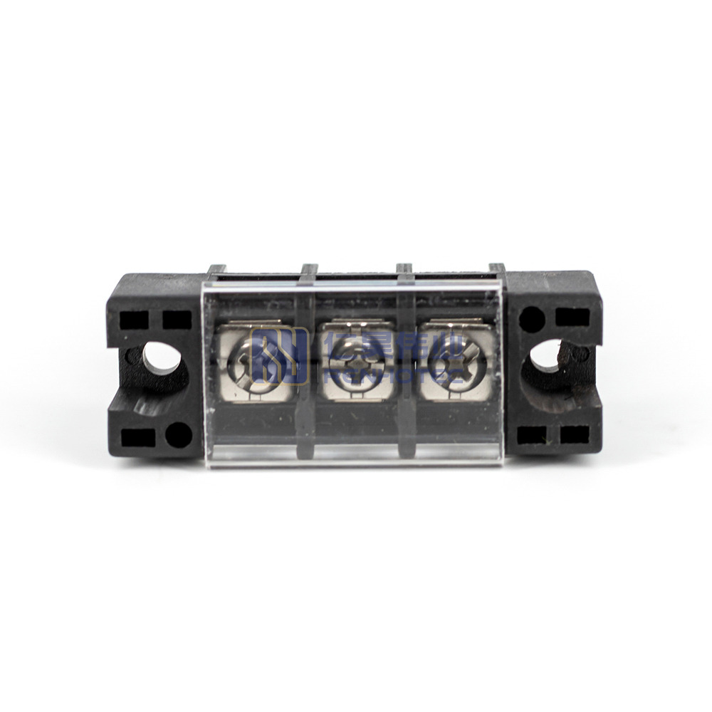
A Terminal Block 3 is an electrical connector that facilitates the safe and secure connection of wires. It is commonly used in electrical systems to organize wire connections, making it easier to manage complex wiring networks. Terminal blocks are widely used in industrial controls, instrumentation panels, power supply units, and various consumer electronics.

Explore Projects Built with terminal block 3

Use Cirkit Designer to design, explore, and prototype these projects online. Some projects support real-time simulation. Click "Open Project" to start designing instantly!
Battery-Powered Multi-Voltage Supply with Barrel Jack Connectors
Image of Battery Setup: A project utilizing terminal block 3 in a practical application
This circuit consists of multiple 9V batteries connected in series and parallel configurations to provide power to three separate 2.1mm barrel jacks. Each barrel jack receives a different combination of series and parallel battery connections to achieve the desired voltage and current levels.
Cirkit Designer LogoOpen Project in Cirkit Designer
Peltier-Controlled Thermal Management System with SPST Switch
Image of Mini car refrigerator circuit: A project utilizing terminal block 3 in a practical application
This circuit consists of multiple Peltier modules and fans connected in parallel to a digital power supply, with a rocker switch (SPST) controlling the power flow to one of the Peltier modules and multiple fans. The 2.1mm Barrel Jack with Terminal Block serves as the power input connector, and the rocker switch allows for selective enabling or disabling of the connected devices. The circuit is designed to provide cooling or heating through the Peltier modules while the fans assist in heat dissipation or air circulation.
Cirkit Designer LogoOpen Project in Cirkit Designer
Modular Power Distribution System with Multiple SMPS Units and 120V Outlet
Image of Cellion-Tesla: A project utilizing terminal block 3 in a practical application
This circuit is designed to convert 240V AC power to both 12V and 24V DC outputs using multiple SMPS units. Terminal blocks are used to organize and distribute the power, while a 120V outlet provides additional AC power access. The circuit is likely used for powering various electronic devices that require different voltage levels.
Cirkit Designer LogoOpen Project in Cirkit Designer
Battery-Powered Relay Control System with Directional Switch
Image of Skema Lampu D2: A project utilizing terminal block 3 in a practical application
This circuit involves a 12V battery powering a relay system controlled by a directional switch. The relays are connected through terminal blocks and are used to switch between different outputs, indicated by the AdaGator Top components.
Cirkit Designer LogoOpen Project in Cirkit Designer

Explore Projects Built with terminal block 3

Use Cirkit Designer to design, explore, and prototype these projects online. Some projects support real-time simulation. Click "Open Project" to start designing instantly!
Image of Battery Setup: A project utilizing terminal block 3 in a practical application
Battery-Powered Multi-Voltage Supply with Barrel Jack Connectors
This circuit consists of multiple 9V batteries connected in series and parallel configurations to provide power to three separate 2.1mm barrel jacks. Each barrel jack receives a different combination of series and parallel battery connections to achieve the desired voltage and current levels.
Cirkit Designer LogoOpen Project in Cirkit Designer
Image of Mini car refrigerator circuit: A project utilizing terminal block 3 in a practical application
Peltier-Controlled Thermal Management System with SPST Switch
This circuit consists of multiple Peltier modules and fans connected in parallel to a digital power supply, with a rocker switch (SPST) controlling the power flow to one of the Peltier modules and multiple fans. The 2.1mm Barrel Jack with Terminal Block serves as the power input connector, and the rocker switch allows for selective enabling or disabling of the connected devices. The circuit is designed to provide cooling or heating through the Peltier modules while the fans assist in heat dissipation or air circulation.
Cirkit Designer LogoOpen Project in Cirkit Designer
Image of Cellion-Tesla: A project utilizing terminal block 3 in a practical application
Modular Power Distribution System with Multiple SMPS Units and 120V Outlet
This circuit is designed to convert 240V AC power to both 12V and 24V DC outputs using multiple SMPS units. Terminal blocks are used to organize and distribute the power, while a 120V outlet provides additional AC power access. The circuit is likely used for powering various electronic devices that require different voltage levels.
Cirkit Designer LogoOpen Project in Cirkit Designer
Image of Skema Lampu D2: A project utilizing terminal block 3 in a practical application
Battery-Powered Relay Control System with Directional Switch
This circuit involves a 12V battery powering a relay system controlled by a directional switch. The relays are connected through terminal blocks and are used to switch between different outputs, indicated by the AdaGator Top components.
Cirkit Designer LogoOpen Project in Cirkit Designer

Common Applications and Use Cases

  • Industrial control systems
  • Electrical distribution panels
  • Consumer electronics
  • HVAC systems
  • Power supply connections

Technical Specifications

Key Technical Details

  • Rated Voltage: Typically up to 600V
  • Rated Current: Varies, often up to 15A or more
  • Wire Size: Accepts a range of wire sizes, often from 26 AWG to 10 AWG
  • Material: Polyamide, thermoplastic, or metal construction for durability and heat resistance
  • Temperature Range: Suitable for operating environments, often between -40°C to 105°C

Pin Configuration and Descriptions

Pin Number Description Notes
1 Wire Entry Connect stripped wire end here
2 Actuation Mechanism Screw or lever to secure wire
3 Electrical Contact Ensures electrical continuity

Usage Instructions

How to Use the Component in a Circuit

  1. Stripping the Wire: Strip approximately 5-7mm of insulation from the wire end to expose the bare conductor.
  2. Inserting the Wire: Loosen the screw or lever on the terminal block, insert the stripped wire end into the wire entry point.
  3. Securing the Wire: Tighten the screw or lever to clamp the wire securely in place. Ensure the wire is held firmly to maintain a good electrical connection.
  4. Connecting Multiple Wires: If daisy-chaining or connecting multiple wires, repeat the process for each wire, ensuring each is securely connected.

Important Considerations and Best Practices

  • Wire Gauge Compatibility: Ensure the wire gauge is compatible with the terminal block's specifications.
  • Torque Specifications: Apply the correct torque to the screws to prevent damage and ensure a secure connection.
  • Regular Inspection: Periodically check the connections for any signs of corrosion, overheating, or loosening.
  • Proper Labeling: Label each connection point to facilitate easy identification and troubleshooting.

Troubleshooting and FAQs

Common Issues Users Might Face

  • Loose Connections: Wires may become loose over time due to vibration or thermal expansion. Regularly check and retighten the connections as necessary.
  • Corrosion: In harsh environments, terminals may corrode, leading to poor connections. Use appropriate protective measures, such as corrosion-resistant materials or coatings.
  • Overheating: Ensure the current rating is not exceeded to prevent overheating of the terminal block.

Solutions and Tips for Troubleshooting

  • Intermittent Connections: If experiencing intermittent connections, check for loose wires or damaged terminals and secure or replace as needed.
  • Difficulty Inserting Wire: If the wire does not insert easily, ensure it is properly stripped and straightened before insertion.

FAQs

Q: Can I use any wire gauge with the Terminal Block 3? A: No, you must use a wire gauge that is within the terminal block's specified range.

Q: How do I know if my connection is secure? A: A secure connection will not allow the wire to be pulled out easily and there should be no visible gaps between the wire and terminal.

Q: Can I reuse a terminal block? A: Yes, terminal blocks are designed to be reusable. However, inspect for any signs of wear or damage before reuse.

Example Code for Arduino UNO Connection

// Example code to demonstrate how to connect an LED to an Arduino UNO
// using a Terminal Block 3 for the ground connection.

void setup() {
  pinMode(13, OUTPUT); // Set the LED pin as an output
}

void loop() {
  digitalWrite(13, HIGH); // Turn on the LED
  delay(1000);           // Wait for 1 second
  digitalWrite(13, LOW);  // Turn off the LED
  delay(1000);           // Wait for 1 second
}

// Note: Connect the anode of the LED to pin 13 of the Arduino UNO.
// Connect the cathode to one side of the Terminal Block 3.
// Connect a wire from the other side of the Terminal Block 3 to the GND pin on the Arduino UNO.

Remember to ensure that the LED's current and voltage requirements are compatible with the Arduino UNO's output specifications, and always use a current-limiting resistor to protect the LED.