How to Use STM32WB55CGU6: Examples, Pinouts, and Specs
Introduction
The STM32WB55CGU6 is a dual-core microcontroller manufactured by STMicroelectronics. It features an ARM Cortex-M4 core for high-performance application processing and an ARM Cortex-M0+ core dedicated to managing low-power tasks. This microcontroller integrates Bluetooth 5.0 connectivity, making it an ideal choice for IoT (Internet of Things) applications. It also includes a wide range of peripherals, such as ADCs, timers, and communication interfaces, to support diverse use cases.
Explore Projects Built with STM32WB55CGU6


Explore Projects Built with STM32WB55CGU6
Common Applications and Use Cases
- IoT devices and smart home applications
- Wearable technology
- Industrial automation and control systems
- Medical devices
- Wireless sensor networks
- Bluetooth Low Energy (BLE) applications
Technical Specifications
Key Technical Details
| Parameter | Value |
|---|---|
| Manufacturer | STMicroelectronics |
| Part Number | WB55CGU6 |
| Core Architecture | Dual-core: ARM Cortex-M4 (application) and ARM Cortex-M0+ (network) |
| Operating Frequency | Cortex-M4: Up to 64 MHz, Cortex-M0+: Up to 32 MHz |
| Flash Memory | 1 MB |
| RAM | 256 KB |
| Bluetooth Version | Bluetooth 5.0 (Low Energy) |
| Operating Voltage | 1.71 V to 3.6 V |
| GPIO Pins | Up to 43 |
| Communication Interfaces | I2C, SPI, UART, USB 2.0, CAN, and more |
| ADC Resolution | 12-bit |
| Operating Temperature Range | -40°C to +85°C |
| Package Type | UFQFPN48 (48-pin) |
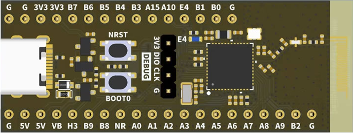
Pin Configuration and Descriptions
The STM32WB55CGU6 comes in a 48-pin UFQFPN package. Below is a summary of key pins and their functions:
| Pin Number | Pin Name | Function Description |
|---|---|---|
| 1 | VDD | Power supply (1.71 V to 3.6 V) |
| 2 | VSS | Ground |
| 3 | PA0 | GPIO/ADC input/Timer input |
| 4 | PA1 | GPIO/ADC input/Timer input |
| 5 | PB6 | I2C1_SCL (I2C clock line) |
| 6 | PB7 | I2C1_SDA (I2C data line) |
| 7 | PC13 | GPIO/External interrupt |
| 8 | NRST | Reset pin |
| 9 | BOOT0 | Boot mode selection |
| 10 | PB3 | SPI1_SCK (SPI clock line) |
| ... | ... | ... (Refer to the datasheet for full details) |
Usage Instructions
How to Use the STM32WB55CGU6 in a Circuit
- Power Supply: Connect the VDD pin to a stable power source (1.71 V to 3.6 V) and the VSS pin to ground.
- Clock Configuration: Use an external crystal oscillator or the internal RC oscillator for clock generation. Ensure proper configuration of the clock tree for both cores.
- Bluetooth Functionality: To enable Bluetooth, configure the Cortex-M0+ core as the network processor. Use the provided ST BLE stack for communication.
- Programming: Use the SWD (Serial Wire Debug) interface for programming and debugging. ST's STM32CubeIDE is recommended for development.
- Peripherals: Configure GPIOs, ADCs, timers, and communication interfaces as needed using the STM32 HAL (Hardware Abstraction Layer) or LL (Low Layer) libraries.
Important Considerations and Best Practices
- Power Management: Utilize the low-power modes (e.g., Stop, Standby) to optimize energy consumption in battery-powered applications.
- RF Design: For Bluetooth functionality, ensure proper antenna design and placement to maximize signal strength and minimize interference.
- Firmware Updates: Use the integrated bootloader for secure firmware updates over UART, USB, or BLE.
- ESD Protection: Implement proper ESD protection on GPIO and communication lines to prevent damage.
Example Code for Arduino UNO Integration
Although the STM32WB55CGU6 is not directly compatible with Arduino UNO, it can communicate with an Arduino via UART. Below is an example of how to send data from the STM32WB55CGU6 to an Arduino UNO:
STM32WB55CGU6 Code (Using HAL Library):
#include "stm32wbxx_hal.h"

// UART handle declaration
UART_HandleTypeDef huart1;

void SystemClock_Config(void);
void MX_USART1_UART_Init(void);

int main(void) {
    HAL_Init(); // Initialize the HAL Library
    SystemClock_Config(); // Configure the system clock
    MX_USART1_UART_Init(); // Initialize UART1

    char message[] = "Hello from STM32WB55CGU6!\r\n";

    while (1) {
        // Transmit message over UART
        HAL_UART_Transmit(&huart1, (uint8_t *)message, sizeof(message) - 1, HAL_MAX_DELAY);
        HAL_Delay(1000); // Wait for 1 second
    }
}

// UART1 initialization function
void MX_USART1_UART_Init(void) {
    huart1.Instance = USART1;
    huart1.Init.BaudRate = 9600;
    huart1.Init.WordLength = UART_WORDLENGTH_8B;
    huart1.Init.StopBits = UART_STOPBITS_1;
    huart1.Init.Parity = UART_PARITY_NONE;
    huart1.Init.Mode = UART_MODE_TX_RX;
    huart1.Init.HwFlowCtl = UART_HWCONTROL_NONE;
    huart1.Init.OverSampling = UART_OVERSAMPLING_16;
    HAL_UART_Init(&huart1);
}
Arduino UNO Code:
void setup() {
  Serial.begin(9600); // Initialize Serial communication at 9600 baud
}

void loop() {
  if (Serial.available()) {
    // Read data from STM32WB55CGU6 and print to Serial Monitor
    String data = Serial.readString();
    Serial.println("Received: " + data);
  }
}
Troubleshooting and FAQs
Common Issues and Solutions
Bluetooth Not Working:
- Ensure the Cortex-M0+ core is properly configured as the network processor.
- Verify that the BLE stack is correctly initialized and running.
Microcontroller Not Booting:
- Check the BOOT0 pin configuration. It should be set to 0 for normal operation.
- Verify the power supply voltage is within the specified range (1.71 V to 3.6 V).
UART Communication Fails:
- Confirm that the baud rate and other UART settings match on both devices.
- Check the physical connections between the STM32WB55CGU6 and the external device.
High Power Consumption:
- Ensure unused peripherals are disabled.
- Use low-power modes when the microcontroller is idle.
FAQs
Q: Can the STM32WB55CGU6 be programmed using Arduino IDE?
A: No, the STM32WB55CGU6 is not natively supported by the Arduino IDE. However, you can use STM32CubeIDE or other compatible tools for development.
Q: Does the STM32WB55CGU6 support over-the-air (OTA) updates?
A: Yes, the STM32WB55CGU6 supports OTA updates via Bluetooth when configured with the appropriate firmware.
Q: What is the maximum range of the Bluetooth module?
A: The Bluetooth range depends on the antenna design and environmental factors but typically ranges from 10 to 50 meters.