How to Use Photon 2: Examples, Pinouts, and Specs
Introduction
The Photon 2 is a powerful Wi-Fi development kit designed for creating connected projects and products. It features a microcontroller with built-in Wi-Fi, making it ideal for Internet of Things (IoT) applications. The Photon 2 is perfect for developers looking to build smart devices, home automation systems, and other connected solutions.
Explore Projects Built with Photon 2
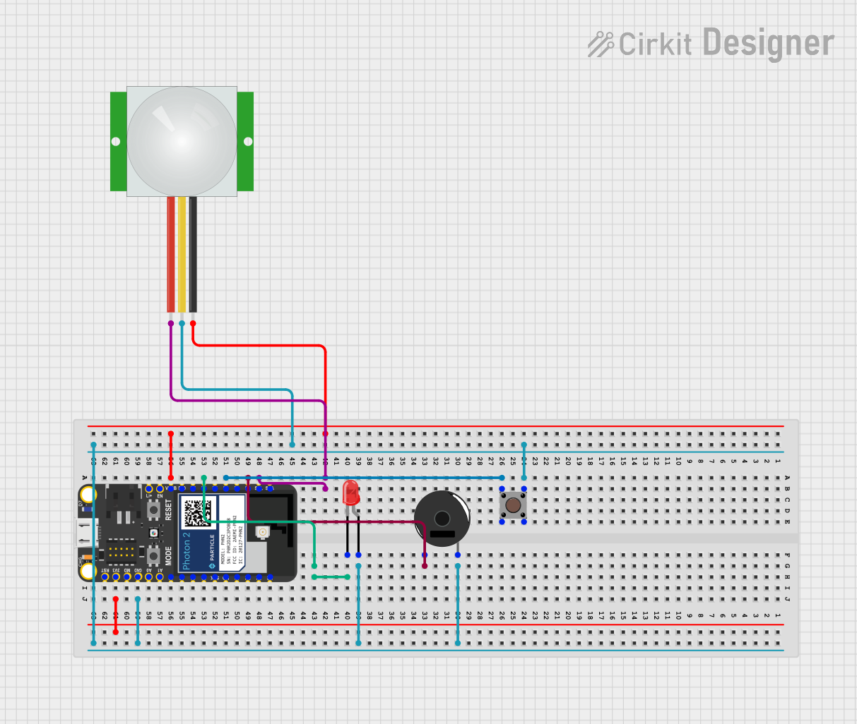
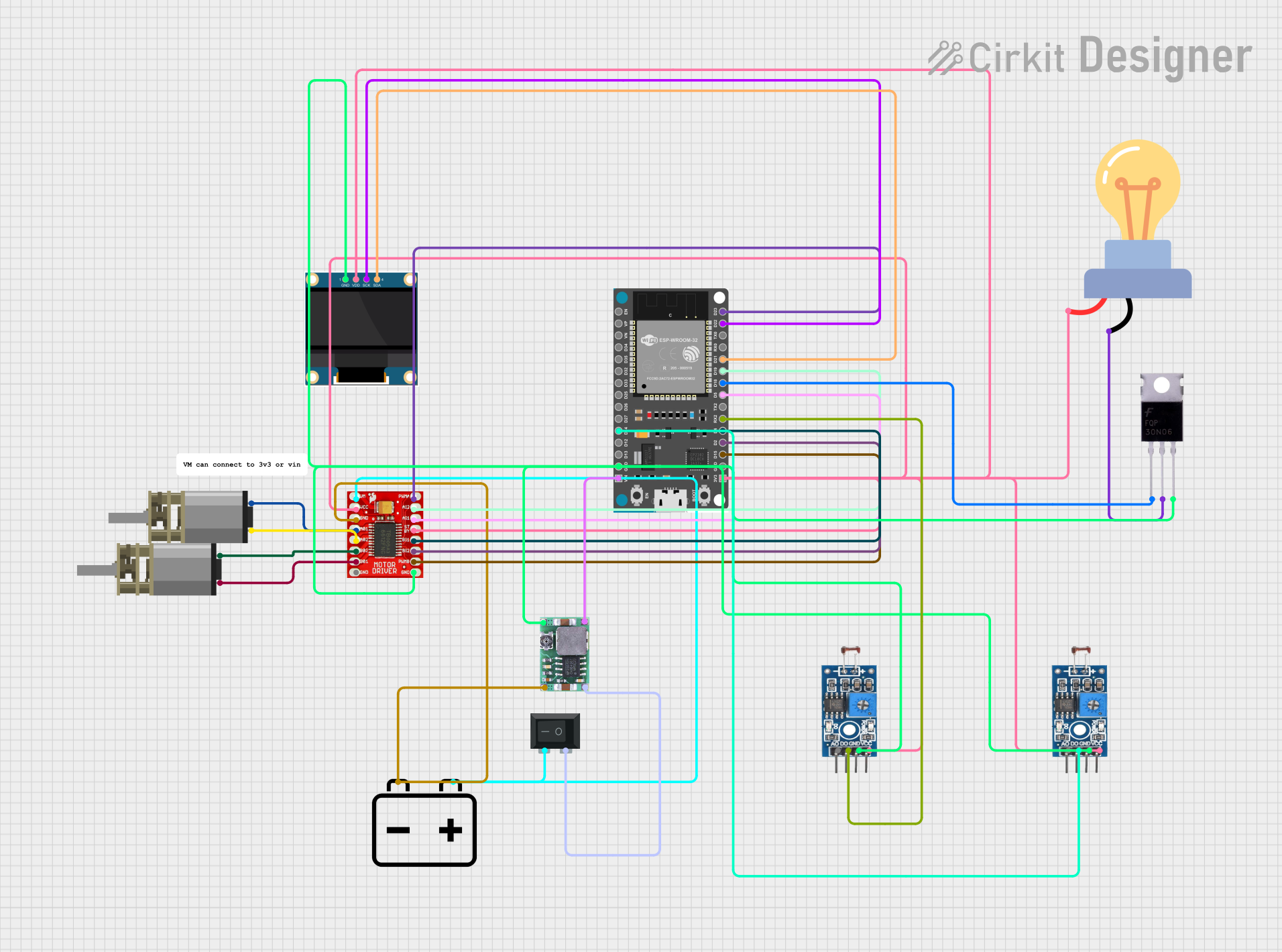


Explore Projects Built with Photon 2
Technical Specifications
Key Technical Details
| Parameter | Value |
|---|---|
| Microcontroller | ARM Cortex-M4 |
| Operating Voltage | 3.3V |
| Input Voltage | 3.6V - 5.5V |
| Digital I/O Pins | 18 |
| Analog Input Pins | 8 |
| Flash Memory | 1MB |
| RAM | 256KB |
| Wi-Fi | 802.11 b/g/n |
| Clock Speed | 120 MHz |
| Dimensions | 36.58mm x 20.32mm |
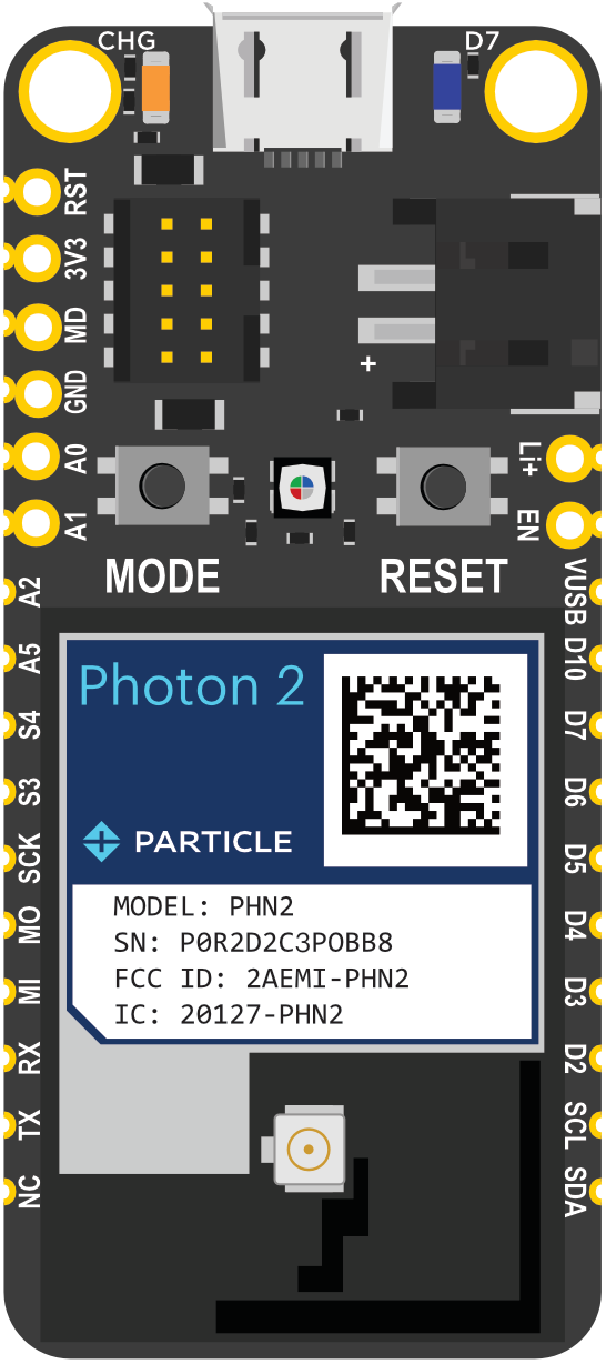
Pin Configuration and Descriptions
| Pin Number | Pin Name | Description |
|---|---|---|
| 1 | VIN | Input voltage (3.6V - 5.5V) |
| 2 | GND | Ground |
| 3 | D0 | Digital I/O |
| 4 | D1 | Digital I/O |
| 5 | D2 | Digital I/O |
| 6 | D3 | Digital I/O |
| 7 | D4 | Digital I/O |
| 8 | D5 | Digital I/O |
| 9 | D6 | Digital I/O |
| 10 | D7 | Digital I/O |
| 11 | A0 | Analog Input |
| 12 | A1 | Analog Input |
| 13 | A2 | Analog Input |
| 14 | A3 | Analog Input |
| 15 | A4 | Analog Input |
| 16 | A5 | Analog Input |
| 17 | A6 | Analog Input |
| 18 | A7 | Analog Input |
Usage Instructions
How to Use the Photon 2 in a Circuit
Powering the Photon 2:
- Connect the VIN pin to a power source (3.6V - 5.5V).
- Connect the GND pin to the ground of the power source.
Connecting to Wi-Fi:
- Use the built-in Wi-Fi module to connect to a Wi-Fi network.
- Configure the Wi-Fi settings using the provided libraries and functions.
Digital I/O:
- Use the digital pins (D0 - D7) for digital input and output operations.
- Configure the pins as input or output using the appropriate functions.
Analog Input:
- Use the analog pins (A0 - A7) to read analog signals.
- Convert the analog signals to digital values using the built-in ADC.
Important Considerations and Best Practices
- Ensure the input voltage does not exceed the specified range (3.6V - 5.5V).
- Use appropriate pull-up or pull-down resistors for digital input pins.
- Avoid connecting high-current devices directly to the digital pins.
- Use decoupling capacitors to reduce noise and improve stability.
Example Code for Arduino UNO
// Example code to connect Photon 2 to Wi-Fi and control an LED

#include <WiFi.h> // Include the Wi-Fi library

const char* ssid = "your_SSID"; // Your Wi-Fi SSID
const char* password = "your_PASSWORD"; // Your Wi-Fi password

void setup() {
  pinMode(D0, OUTPUT); // Set D0 as an output pin
  Serial.begin(115200); // Initialize serial communication

  // Connect to Wi-Fi
  Serial.print("Connecting to ");
  Serial.println(ssid);
  WiFi.begin(ssid, password);

  while (WiFi.status() != WL_CONNECTED) {
    delay(1000);
    Serial.print(".");
  }

  Serial.println("");
  Serial.println("WiFi connected");
  Serial.println("IP address: ");
  Serial.println(WiFi.localIP());
}

void loop() {
  digitalWrite(D0, HIGH); // Turn the LED on
  delay(1000); // Wait for a second
  digitalWrite(D0, LOW); // Turn the LED off
  delay(1000); // Wait for a second
}
Troubleshooting and FAQs
Common Issues Users Might Face
Wi-Fi Connection Issues:
- Ensure the SSID and password are correct.
- Check if the Wi-Fi network is within range.
- Restart the Photon 2 and try reconnecting.
Power Supply Problems:
- Verify the input voltage is within the specified range.
- Check for loose connections or faulty power sources.
Digital I/O Malfunctions:
- Ensure the pins are configured correctly as input or output.
- Check for short circuits or incorrect wiring.
Solutions and Tips for Troubleshooting
Wi-Fi Connection:
- Use a Wi-Fi analyzer to check signal strength and interference.
- Update the firmware to the latest version.
Power Supply:
- Use a stable and regulated power supply.
- Add decoupling capacitors to filter out noise.
Digital I/O:
- Use pull-up or pull-down resistors to stabilize input pins.
- Avoid connecting high-current devices directly to the pins.
By following this documentation, users can effectively utilize the Photon 2 for their IoT projects and connected solutions. Whether you are a beginner or an experienced developer, the Photon 2 offers a versatile and powerful platform for creating innovative and smart devices.