How to Use 4S 40A BMS: Examples, Pinouts, and Specs
Introduction
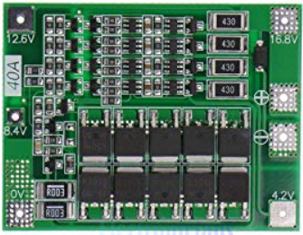
The 4S 40A Battery Management System (BMS) is a crucial component designed for managing 4-cell (4S) lithium battery packs. It ensures the safe operation of the battery pack by monitoring and balancing the individual cells, and providing protection against overcharge, over-discharge, and short circuits. This BMS is capable of handling up to 40 amps of current, making it suitable for high-power applications.
Explore Projects Built with 4S 40A BMS


Explore Projects Built with 4S 40A BMS
Common Applications and Use Cases
- Electric vehicles (e-bikes, e-scooters)
- Renewable energy storage systems (solar, wind)
- Uninterruptible power supplies (UPS)
- Portable power banks
- Robotics and drones
Technical Specifications
Key Technical Details
| Parameter | Value |
|---|---|
| Battery Configuration | 4S (4 cells in series) |
| Maximum Continuous Current | 40A |
| Overcharge Protection | 4.25V ± 0.05V per cell |
| Over-discharge Protection | 2.8V ± 0.05V per cell |
| Balance Current | 60mA |
| Operating Temperature | -20°C to 60°C |
| Storage Temperature | -40°C to 80°C |
| Dimensions | 60mm x 45mm x 10mm |
Pin Configuration and Descriptions
| Pin Number | Pin Name | Description |
|---|---|---|
| 1 | B- | Battery negative terminal |
| 2 | B1 | Connection to the positive terminal of cell 1 |
| 3 | B2 | Connection to the positive terminal of cell 2 |
| 4 | B3 | Connection to the positive terminal of cell 3 |
| 5 | B4 | Connection to the positive terminal of cell 4 |
| 6 | P- | Power output negative terminal |
| 7 | P+ | Power output positive terminal |
Usage Instructions
How to Use the Component in a Circuit
Wiring the BMS:
- Connect the B- pin to the negative terminal of the battery pack.
- Connect the B1 pin to the positive terminal of the first cell.
- Connect the B2 pin to the positive terminal of the second cell.
- Connect the B3 pin to the positive terminal of the third cell.
- Connect the B4 pin to the positive terminal of the fourth cell.
- Connect the P- pin to the negative terminal of the load or charger.
- Connect the P+ pin to the positive terminal of the load or charger.
Balancing and Protection:
- The BMS will automatically balance the cells during charging.
- It will cut off the charging or discharging process if any cell exceeds the overcharge or over-discharge voltage limits.
Important Considerations and Best Practices
- Ensure that all connections are secure and correct to prevent damage to the BMS or battery pack.
- Avoid exposing the BMS to extreme temperatures or moisture.
- Regularly check the battery pack for any signs of damage or wear.
- Use appropriate fuses and circuit breakers to provide additional protection.
Troubleshooting and FAQs
Common Issues Users Might Face
BMS Not Balancing Cells:
- Solution: Ensure that the BMS is properly connected to all cells. Check for any loose or broken connections.
Overcharge/Over-discharge Protection Not Working:
- Solution: Verify that the voltage thresholds are within the specified range. Replace the BMS if it is faulty.
BMS Overheating:
- Solution: Ensure that the BMS is not exposed to high ambient temperatures. Provide adequate ventilation and cooling.
Solutions and Tips for Troubleshooting
- Check Connections: Always double-check all connections to ensure they are secure and correct.
- Monitor Cell Voltages: Use a multimeter to monitor the voltages of individual cells to ensure they are within the safe range.
- Inspect for Damage: Regularly inspect the BMS and battery pack for any signs of physical damage or wear.
Example Code for Arduino UNO
If you are using the 4S 40A BMS with an Arduino UNO to monitor the battery pack, you can use the following example code to read the cell voltages:
// Example code to read cell voltages using Arduino UNO
// Connect the cell voltage outputs to analog pins A0 to A3

const int cell1Pin = A0;
const int cell2Pin = A1;
const int cell3Pin = A2;
const int cell4Pin = A3;

void setup() {
  Serial.begin(9600); // Initialize serial communication
}

void loop() {
  float cell1Voltage = analogRead(cell1Pin) * (5.0 / 1023.0) * 4.2;
  float cell2Voltage = analogRead(cell2Pin) * (5.0 / 1023.0) * 4.2;
  float cell3Voltage = analogRead(cell3Pin) * (5.0 / 1023.0) * 4.2;
  float cell4Voltage = analogRead(cell4Pin) * (5.0 / 1023.0) * 4.2;

  Serial.print("Cell 1 Voltage: ");
  Serial.println(cell1Voltage);
  Serial.print("Cell 2 Voltage: ");
  Serial.println(cell2Voltage);
  Serial.print("Cell 3 Voltage: ");
  Serial.println(cell3Voltage);
  Serial.print("Cell 4 Voltage: ");
  Serial.println(cell4Voltage);

  delay(1000); // Wait for 1 second before the next reading
}
This code reads the voltages of the four cells and prints them to the serial monitor. Make sure to adjust the voltage scaling factor based on your specific setup.
This documentation provides a comprehensive guide to understanding, using, and troubleshooting the 4S 40A BMS. Whether you are a beginner or an experienced user, this guide will help you ensure the safe and efficient operation of your lithium battery pack.