How to Use LED: Two Pin (yellow): Examples, Pinouts, and Specs
Introduction
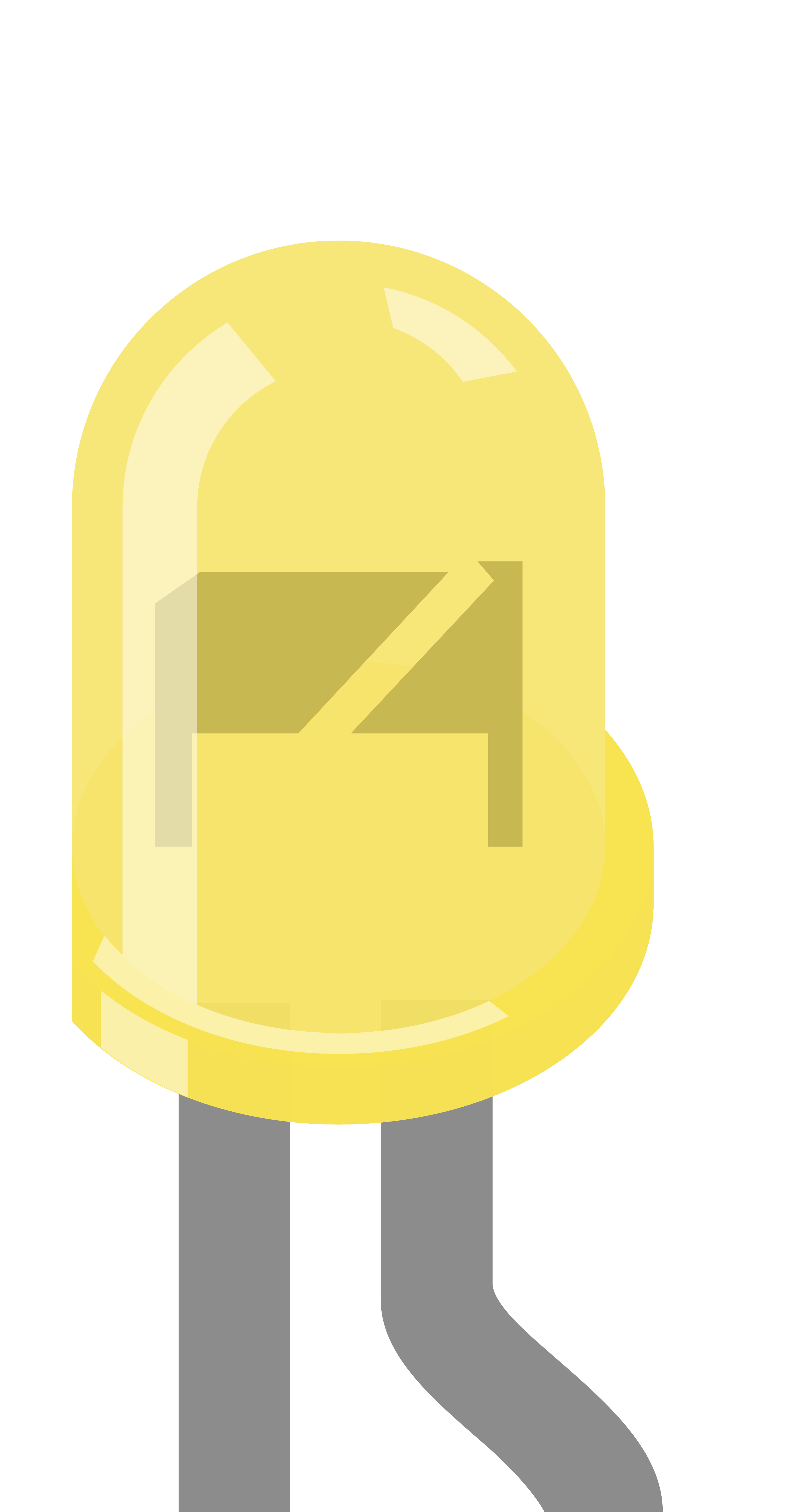
A yellow LED (Light-Emitting Diode) with two pins is a semiconductor light source that emits yellow light when an electric current passes through it. LEDs are widely used in various applications due to their low power consumption, long life, and compact size. Yellow LEDs are commonly used for indicators, decorative lighting, and in electronic devices to convey status or alerts.
Explore Projects Built with LED: Two Pin (yellow)

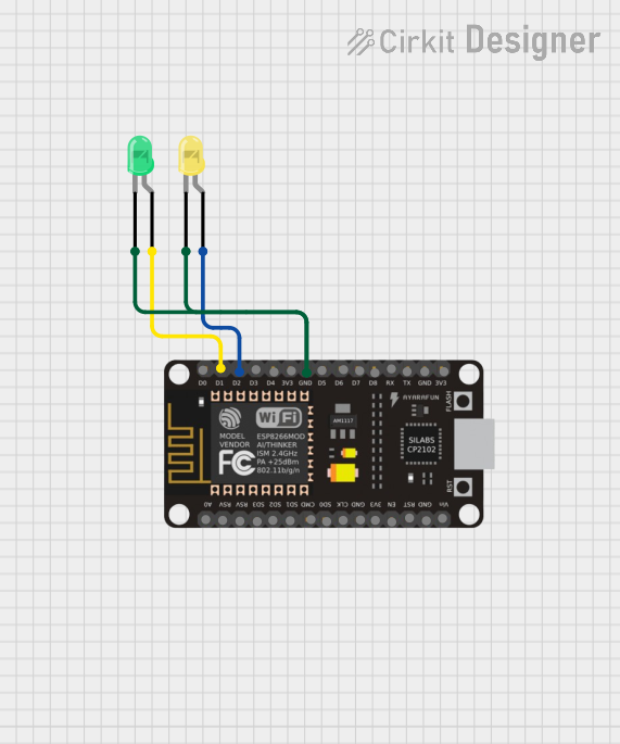
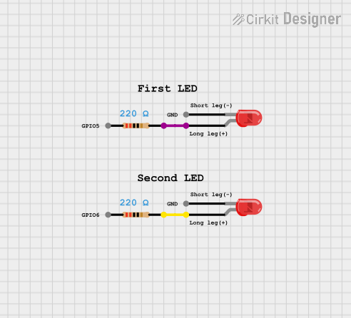
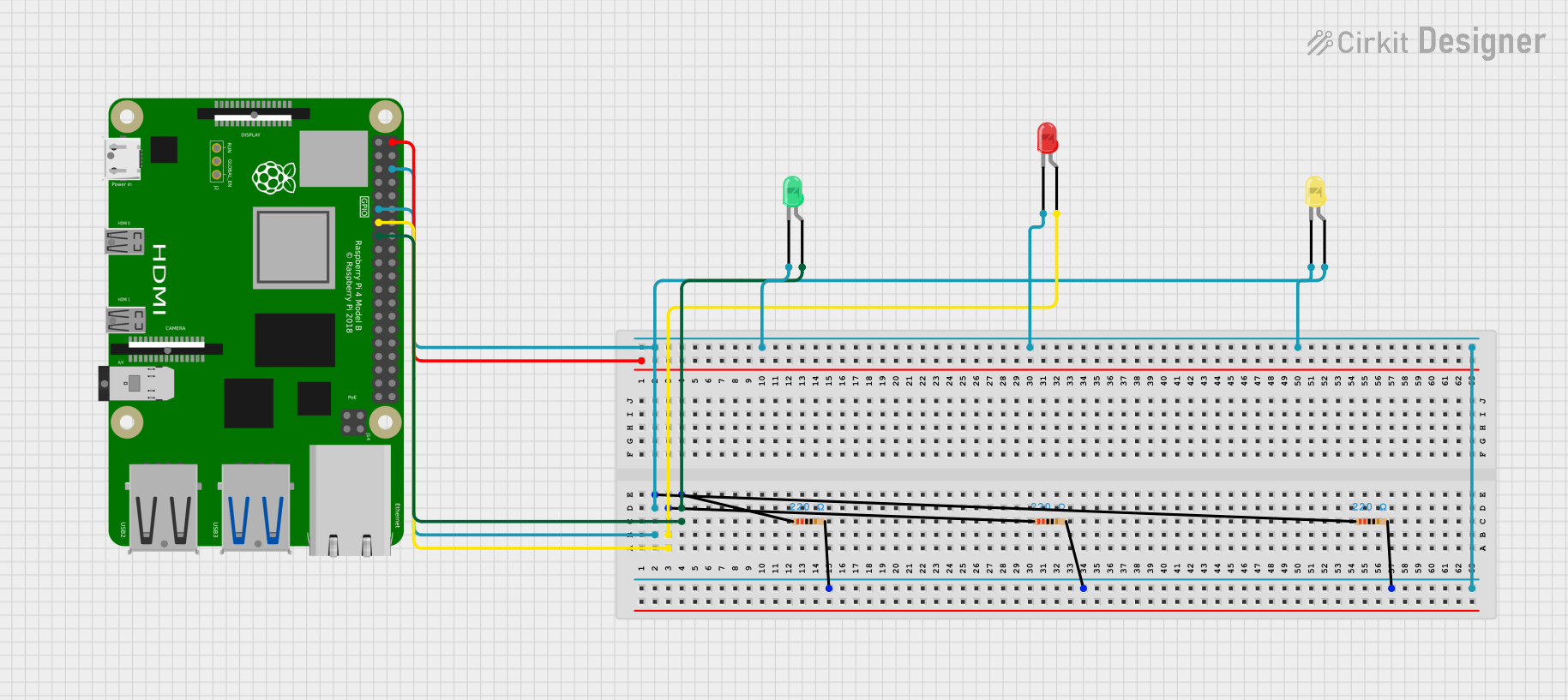
Explore Projects Built with LED: Two Pin (yellow)
Technical Specifications
Key Technical Details
- Forward Voltage (Vf): Typically 2.0V to 2.2V
- Forward Current (If): Recommended 20mA (max. 30mA)
- Luminous Intensity: Dependent on current and manufacturer, typically around 2-20 mcd (millicandela)
- Wavelength: Approximately 585 to 595 nm (nanometers)
- Viewing Angle: Typically between 30° to 60°
Pin Configuration and Descriptions
| Pin Number | Name | Description |
|---|---|---|
| 1 | Anode (+) | The longer pin, to be connected to the positive supply voltage. |
| 2 | Cathode (-) | The shorter pin, to be connected to the ground (0V). |
Usage Instructions
How to Use the LED in a Circuit
- Identify the Pins: Determine the anode and cathode of the LED. The longer leg is the anode, and the shorter leg is the cathode.
- Current Limiting Resistor: To prevent damage to the LED, use a current-limiting resistor in series with the anode or cathode.
- Calculate the resistor value using Ohm's law:
R = (Vs - Vf) / If, whereVsis the supply voltage.
- Calculate the resistor value using Ohm's law:
- Circuit Connection: Connect the anode to the positive voltage through the resistor, and the cathode to the ground.
- Power Supply: Ensure that the power supply does not exceed the recommended forward voltage and current.
Important Considerations and Best Practices
- Resistor Calculation: Always calculate the current-limiting resistor value to prevent exceeding the maximum forward current.
- Polarity: Connecting the LED in reverse polarity will prevent it from lighting and can cause damage if reverse voltage exceeds the maximum rating.
- Heat Dissipation: For high-brightness applications, consider heat dissipation methods to prolong the LED's life.
Example Circuit with Arduino UNO
// Define the LED pin
const int ledPin = 13; // Most Arduino UNO boards have an onboard LED on pin 13

void setup() {
  pinMode(ledPin, OUTPUT); // Set the LED pin as an output
}

void loop() {
  digitalWrite(ledPin, HIGH); // Turn the LED on
  delay(1000);                // Wait for a second
  digitalWrite(ledPin, LOW);  // Turn the LED off
  delay(1000);                // Wait for a second
}
Troubleshooting and FAQs
Common Issues
- LED Not Lighting Up: Check the polarity of the LED and ensure the current-limiting resistor is correctly calculated and placed.
- LED Burnt Out: This usually occurs due to excessive current. Verify that the current-limiting resistor is appropriate for the supply voltage.
- Dim LED: If the LED is dimmer than expected, check if the supply voltage is too low or if the current-limiting resistor value is too high.
Solutions and Tips
- Polarity Check: Use a multimeter to check the continuity of the LED pins to ensure correct polarity.
- Resistor Value: Double-check the resistor value calculation and ensure it is suitable for the LED's forward voltage and desired forward current.
- Supply Voltage: Verify that the supply voltage is within the recommended range for the LED.
FAQs
Q: Can I connect multiple LEDs in series? A: Yes, but ensure that the supply voltage is high enough to account for the sum of the forward voltages of all LEDs, and use a single current-limiting resistor for the series circuit.
Q: What happens if I don't use a resistor with the LED? A: Without a resistor, the LED may draw excessive current, leading to overheating and potential failure.
Q: Can I use a variable resistor to adjust the LED brightness? A: Yes, a potentiometer can be used to vary the resistance and, consequently, the LED brightness. However, do not exceed the maximum forward current.