How to Use USB-C Breakout: Examples, Pinouts, and Specs
Introduction
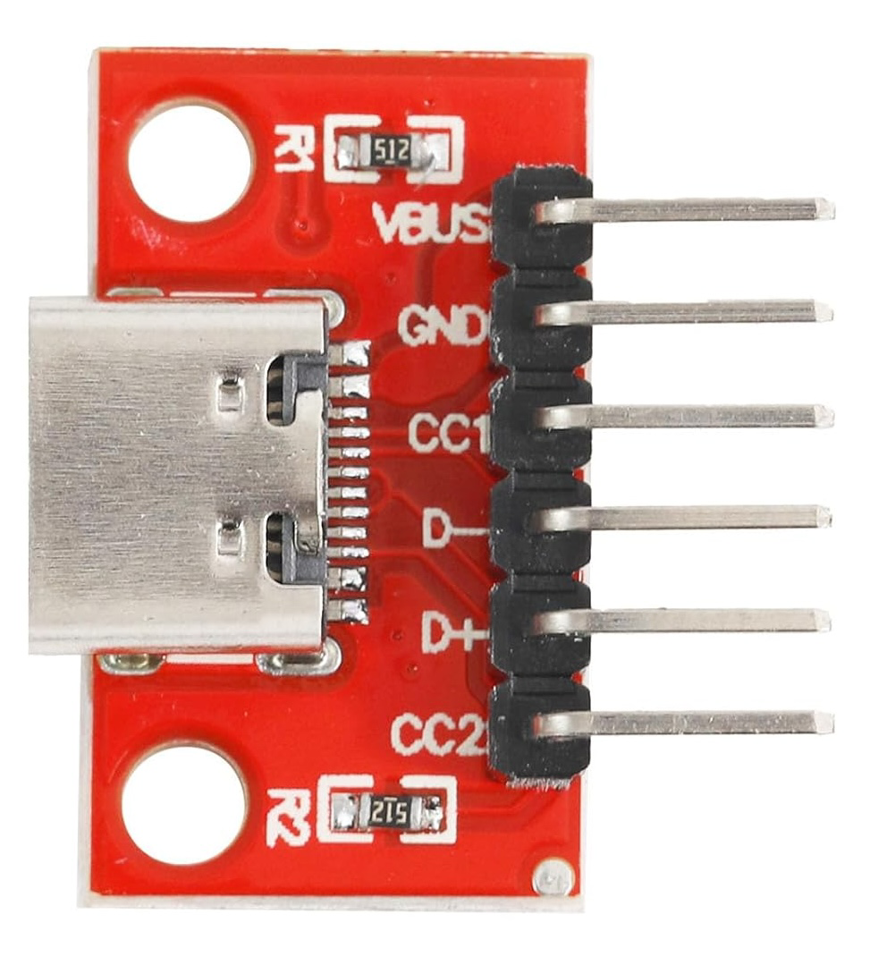
The USB-C Breakout by Cermant is a compact and versatile breakout board designed to provide easy access to the pins of a USB-C connector. This component simplifies prototyping and testing of USB-C connections, enabling developers to integrate USB-C functionality into their projects without the need for complex soldering or custom PCBs.
Explore Projects Built with USB-C Breakout


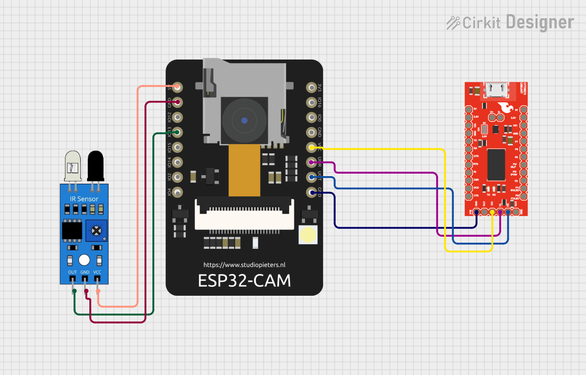
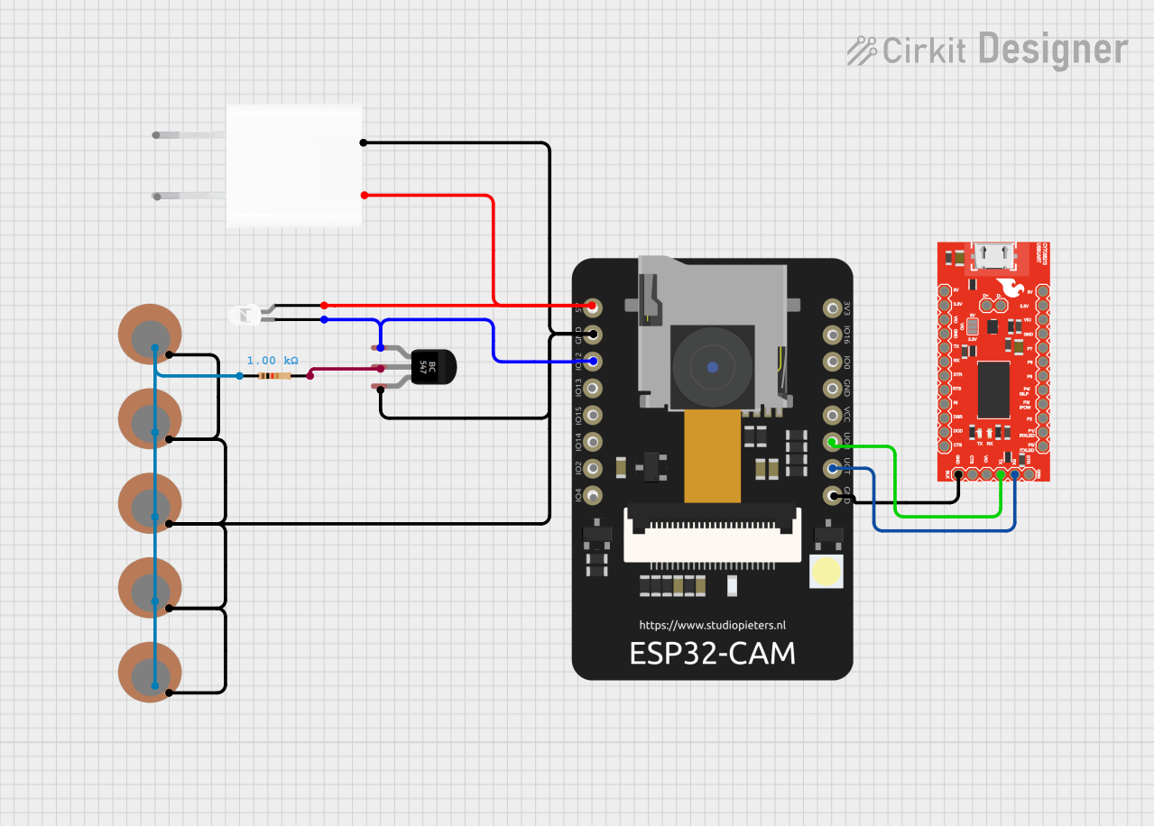
Explore Projects Built with USB-C Breakout
Common Applications and Use Cases
- Prototyping USB-C power delivery (PD) circuits
- Testing USB-C data transfer capabilities
- Developing USB-C-based devices, such as chargers, hubs, or peripherals
- Educational purposes for learning USB-C pinout and functionality
Technical Specifications
The USB-C Breakout board by Cermant is designed to meet the needs of developers working with USB-C technology. Below are the key technical details:
Key Specifications
| Parameter | Value |
|---|---|
| Connector Type | USB Type-C (Receptacle) |
| Voltage Rating | 5V to 20V (depending on application) |
| Current Rating | Up to 5A (depending on cable and source) |
| Supported Protocols | USB 2.0, USB 3.1, USB Power Delivery |
| PCB Dimensions | 25mm x 20mm |
| Mounting Style | Through-hole or breadboard-compatible |
| Operating Temperature | -40°C to 85°C |
Pin Configuration and Descriptions
The USB-C connector has 24 pins, but the breakout board exposes only the most commonly used pins for prototyping. Below is the pin configuration:
| Pin Name | Pin Number | Description |
|---|---|---|
| GND | Multiple | Ground connection |
| VBUS | Multiple | Power input (5V to 20V, depending on source) |
| CC1 | A5 | Configuration channel 1 for USB-C communication |
| CC2 | B5 | Configuration channel 2 for USB-C communication |
| D+ | A6, B6 | USB 2.0 data positive |
| D- | A7, B7 | USB 2.0 data negative |
| TX1+ | A2 | USB 3.1 SuperSpeed transmit positive (lane 1) |
| TX1- | A3 | USB 3.1 SuperSpeed transmit negative (lane 1) |
| RX1+ | B2 | USB 3.1 SuperSpeed receive positive (lane 1) |
| RX1- | B3 | USB 3.1 SuperSpeed receive negative (lane 1) |
Note: Not all pins are exposed on the breakout board. Refer to the manufacturer's datasheet for the full USB-C pinout.
Usage Instructions
How to Use the USB-C Breakout in a Circuit
Connect the Breakout Board to a Breadboard:
- The breakout board is designed to be breadboard-compatible. Insert the pins into the breadboard for easy prototyping.
Power the Board:
- Connect the VBUS pin to your power source (5V to 20V, depending on your application).
- Ensure the GND pin is connected to the ground of your circuit.
Use the CC Pins for Configuration:
- The CC1 and CC2 pins are used to detect the orientation of the USB-C cable and negotiate power delivery. Use appropriate resistors (typically 5.1kΩ) to configure the desired power profile.
Connect Data Lines:
- Use the D+ and D- pins for USB 2.0 communication.
- For USB 3.1 SuperSpeed communication, connect the TX and RX pins as needed.
Test Your Circuit:
- Verify all connections before powering the circuit. Use a multimeter to check for shorts or incorrect wiring.
Important Considerations and Best Practices
- Voltage and Current Ratings: Ensure that the power source and connected devices do not exceed the breakout board's voltage and current ratings.
- Cable Orientation: USB-C cables are reversible. Use the CC pins to detect the cable orientation and configure the circuit accordingly.
- Data Protocols: If using USB 3.1, ensure that your circuit supports the required SuperSpeed data rates.
- ESD Protection: Consider adding external ESD protection components to safeguard the breakout board and connected devices.
Example: Using the USB-C Breakout with Arduino UNO
Below is an example of using the USB-C breakout to power an Arduino UNO and read data from a USB-C device:
// Example: Reading data from a USB-C device using Arduino UNO
// Ensure the USB-C breakout is connected to the Arduino as follows:
// VBUS -> 5V, GND -> GND, D+ -> Pin 2, D- -> Pin 3

#include <SoftwareSerial.h>

// Define pins for USB-C data lines
#define USB_DPLUS 2
#define USB_DMINUS 3

// Initialize SoftwareSerial for USB-C communication
SoftwareSerial usbSerial(USB_DPLUS, USB_DMINUS);

void setup() {
  // Start serial communication
  Serial.begin(9600);
  usbSerial.begin(9600);

  // Print a message to indicate setup is complete
  Serial.println("USB-C Breakout Example: Ready to receive data.");
}

void loop() {
  // Check if data is available from the USB-C device
  if (usbSerial.available()) {
    // Read data from the USB-C device
    char data = usbSerial.read();

    // Print the received data to the Serial Monitor
    Serial.print("Received: ");
    Serial.println(data);
  }
}
Note: This example assumes the USB-C device communicates using USB 2.0 protocols. For USB 3.1 or Power Delivery, additional hardware and libraries may be required.
Troubleshooting and FAQs
Common Issues and Solutions
No Power on VBUS Pin:
- Cause: The USB-C cable may not be properly connected, or the power source may not be active.
- Solution: Check the cable connection and ensure the power source is functioning.
Incorrect Voltage on VBUS:
- Cause: The CC pins are not configured correctly for power delivery.
- Solution: Use appropriate resistors (e.g., 5.1kΩ) on the CC pins to negotiate the desired voltage.
Data Communication Fails:
- Cause: Incorrect wiring of D+ and D- pins or unsupported protocol.
- Solution: Verify the connections and ensure the device supports the desired USB protocol.
Overheating:
- Cause: Excessive current draw or short circuit.
- Solution: Check the circuit for shorts and ensure the current does not exceed 5A.
FAQs
Q: Can this breakout board be used for USB Power Delivery (PD)?
A: Yes, the breakout board supports USB PD, but you must configure the CC pins with appropriate resistors to negotiate the desired voltage and current.
Q: Does the board support USB 3.1 SuperSpeed?
A: Yes, the breakout exposes the TX and RX pins required for USB 3.1 SuperSpeed communication.
Q: Is the breakout board compatible with all USB-C cables?
A: The board is compatible with standard USB-C cables, but ensure the cable supports the required power and data specifications for your application.