Cirkit Designer Logo
Cirkit Designer
Your all-in-one circuit design IDE
Home / 
Component Documentation

How to Use RJ45: Examples, Pinouts, and Specs

Image of RJ45
Cirkit Designer LogoDesign with RJ45 in Cirkit Designer

Introduction

The RJ45 connector is a widely used interface in networking applications, particularly for Ethernet communications. It is an 8-pin connector that allows computers, routers, switches, and other network devices to communicate with each other over a network. When used with an Arduino Uno, the RJ45 can enable the microcontroller to connect to a local area network (LAN) or the internet, allowing for a variety of network-related projects and applications such as home automation, IoT devices, and remote data logging.

Explore Projects Built with RJ45

Use Cirkit Designer to design, explore, and prototype these projects online. Some projects support real-time simulation. Click "Open Project" to start designing instantly!
ESP32-Based RJ45 Cable Tester with LED Indicators and Buzzer
Image of RJ45 TESTER: A project utilizing RJ45 in a practical application
This circuit is a cable tester using two ESP32 microcontrollers to check the continuity and measure the length of RJ45 cables. It includes LEDs, a buzzer, and an LCD for visual and auditory feedback, and a pushbutton to initiate the test. The microcontrollers control the LEDs, buzzer, and LCD, and read the state of the RJ45 pins to determine connectivity and cable length.
Cirkit Designer LogoOpen Project in Cirkit Designer
Optiplex Micro and PoE Camera Surveillance System with Ethernet Switching
Image of Engine Mounts Wiring: A project utilizing RJ45 in a practical application
This circuit describes a networked system where an Optiplex Micro computer is powered by a PC Power Supply and connected to a PC Screen via HDMI for display output. The computer is networked through an Ethernet Switch, which also connects to two PoE Cameras and a Toyopuc PLC. The Ethernet Switch is powered by a PoE PSU 48V DC, and all AC-powered devices are connected to a common 220V AC source.
Cirkit Designer LogoOpen Project in Cirkit Designer
FTDI to UART Adapter with J26 Connector
Image of J26 CLOSEUP: A project utilizing RJ45 in a practical application
This circuit connects an FTDI USB-to-serial converter to a standard serial interface via a J26 connector. It facilitates serial communication by linking the ground, transmit, receive, data terminal ready, and request to send signals between the FTDI chip and the J26 connector.
Cirkit Designer LogoOpen Project in Cirkit Designer
Raspberry Pi 5 and TTL Serial JPEG Camera for Image Capture
Image of coe333: A project utilizing RJ45 in a practical application
This circuit connects a TTL Serial JPEG Camera to a Raspberry Pi 5, enabling the Raspberry Pi to receive image data from the camera via UART communication. The camera's GND, RX, and TX pins are connected to the Raspberry Pi's GND, GPIO 14, and GPIO 15 pins, respectively.
Cirkit Designer LogoOpen Project in Cirkit Designer

Explore Projects Built with RJ45

Use Cirkit Designer to design, explore, and prototype these projects online. Some projects support real-time simulation. Click "Open Project" to start designing instantly!
Image of RJ45 TESTER: A project utilizing RJ45 in a practical application
ESP32-Based RJ45 Cable Tester with LED Indicators and Buzzer
This circuit is a cable tester using two ESP32 microcontrollers to check the continuity and measure the length of RJ45 cables. It includes LEDs, a buzzer, and an LCD for visual and auditory feedback, and a pushbutton to initiate the test. The microcontrollers control the LEDs, buzzer, and LCD, and read the state of the RJ45 pins to determine connectivity and cable length.
Cirkit Designer LogoOpen Project in Cirkit Designer
Image of Engine Mounts Wiring: A project utilizing RJ45 in a practical application
Optiplex Micro and PoE Camera Surveillance System with Ethernet Switching
This circuit describes a networked system where an Optiplex Micro computer is powered by a PC Power Supply and connected to a PC Screen via HDMI for display output. The computer is networked through an Ethernet Switch, which also connects to two PoE Cameras and a Toyopuc PLC. The Ethernet Switch is powered by a PoE PSU 48V DC, and all AC-powered devices are connected to a common 220V AC source.
Cirkit Designer LogoOpen Project in Cirkit Designer
Image of J26 CLOSEUP: A project utilizing RJ45 in a practical application
FTDI to UART Adapter with J26 Connector
This circuit connects an FTDI USB-to-serial converter to a standard serial interface via a J26 connector. It facilitates serial communication by linking the ground, transmit, receive, data terminal ready, and request to send signals between the FTDI chip and the J26 connector.
Cirkit Designer LogoOpen Project in Cirkit Designer
Image of coe333: A project utilizing RJ45 in a practical application
Raspberry Pi 5 and TTL Serial JPEG Camera for Image Capture
This circuit connects a TTL Serial JPEG Camera to a Raspberry Pi 5, enabling the Raspberry Pi to receive image data from the camera via UART communication. The camera's GND, RX, and TX pins are connected to the Raspberry Pi's GND, GPIO 14, and GPIO 15 pins, respectively.
Cirkit Designer LogoOpen Project in Cirkit Designer

Technical Specifications

General Specifications

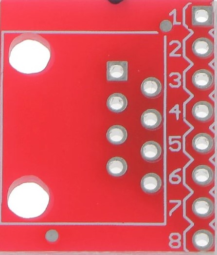
  • Type: 8P8C (8 position, 8 contact)
  • Category: Typically Cat 5, Cat 5e, Cat 6, Cat 6a
  • Compatibility: Ethernet (10BASE-T, 100BASE-TX, 1000BASE-T, etc.)
  • Durability: Typically rated for 1,000 to 2,000 mating cycles
  • Operating Temperature: Varies by manufacturer, commonly -10°C to +60°C

Pin Configuration and Descriptions

Pin Number Wire Color (T568B) Wire Color (T568A) Signal Name
1 Orange/White Green/White Transmit Data +
2 Orange Green Transmit Data -
3 Green/White Orange/White Receive Data +
4 Blue Blue Not Used
5 Blue/White Blue/White Not Used
6 Green Orange Receive Data -
7 Brown/White Brown/White Not Used
8 Brown Brown Not Used

Note: The Arduino Uno does not have a built-in RJ45 connector. To use an RJ45 with the Arduino Uno, an Ethernet shield or module that is compatible with the Arduino Uno must be used.

Usage Instructions

Connecting RJ45 to Arduino Uno

  1. Ethernet Shield: Attach an Ethernet shield to the Arduino Uno. This shield typically comes with an onboard RJ45 connector.
  2. Wiring: If using an Ethernet module, wire the module to the Arduino Uno according to the module's datasheet.
  3. Library: Include the Ethernet library in your Arduino sketch to enable Ethernet functionality.
  4. Initialization: Initialize the Ethernet client in your setup function.
  5. DHCP or Static IP: Configure the network settings to use DHCP or a static IP address.

Best Practices

  • Use quality cables to reduce noise and improve communication reliability.
  • Ensure proper grounding and cable shielding to minimize electromagnetic interference.
  • Avoid running Ethernet cables parallel to power cables to prevent crosstalk.
  • Keep the RJ45 connector and Ethernet cables away from moisture and extreme temperatures.

Example Code for Arduino Uno

#include <SPI.h>
#include <Ethernet.h>

// MAC address for the Ethernet shield (must be unique on the network)
byte mac[] = { 0xDE, 0xAD, 0xBE, 0xEF, 0xFE, 0xED };

// IP address for the Ethernet shield (if not using DHCP)
IPAddress ip(192, 168, 1, 177);

// Initialize the Ethernet client library
EthernetClient client;

void setup() {
  // Start the Ethernet connection
  Ethernet.begin(mac, ip);
}

void loop() {
  // Your code here to send/receive data over the network
}

Note: The above code assumes a static IP configuration. For DHCP, use Ethernet.begin(mac) without specifying an IP address.

Troubleshooting and FAQs

Common Issues

  • No Network Connection: Ensure the Ethernet cable is properly connected and the router/switch is operational.
  • IP Conflict: Verify that the static IP address is not already in use on the network.
  • Library Errors: Make sure the Ethernet library is correctly included and that the correct board is selected in the Arduino IDE.

FAQs

Q: Can I use the RJ45 connector for non-Ethernet applications? A: While the RJ45 is standardized for Ethernet, it can be used for other applications, but this is not common and not recommended for beginners.

Q: How do I know if my Ethernet shield is working? A: Most Ethernet shields have LEDs that indicate power, connection, and data transfer status. Check these LEDs for proper operation.

Q: Can I connect my Arduino Uno directly to the internet using RJ45? A: Yes, with an Ethernet shield or module, you can connect the Arduino Uno to the internet for various online applications.

Remember to always refer to the specific Ethernet shield or module documentation for detailed instructions and capabilities.