
How to Use MAX1555 Lithium Charger IC: Examples, Pinouts, and Specs
 Design with MAX1555 Lithium Charger IC in Cirkit Designer
Introduction
The MAX1555 is a highly integrated lithium-ion battery charger IC designed for portable applications. It features a linear charging architecture, enabling efficient charging with minimal external components. The IC supports both USB and DC input power sources, making it versatile for a wide range of applications. Key features include thermal regulation, charge status indication, and a programmable charge current, ensuring safe and reliable battery management.
Explore Projects Built with MAX1555 Lithium Charger IC
 Open Project in Cirkit Designer
 Open Project in Cirkit Designer
 Open Project in Cirkit Designer
 Open Project in Cirkit Designer
Explore Projects Built with MAX1555 Lithium Charger IC
Open Project in Cirkit DesignerOpen Project in Cirkit DesignerOpen Project in Cirkit DesignerOpen Project in Cirkit DesignerCommon Applications
- Portable electronic devices (e.g., smartphones, MP3 players, and handheld gadgets)
- Wearable devices
- Battery-powered IoT devices
- Backup power systems
- Development boards and prototyping projects
Technical Specifications
Key Technical Details
| Parameter | Value |
|---|---|
| Input Voltage Range | 4.1V to 7.0V |
| Charging Current (USB) | 100mA (default) |
| Charging Current (DC) | 280mA (default) |
| Battery Regulation Voltage | 4.2V ± 1% |
| Thermal Regulation | 110°C (typical) |
| Operating Temperature Range | -40°C to +85°C |
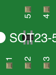
| Package Type | SOT23-5 |
Pin Configuration and Descriptions
| Pin Number | Pin Name | Description |
|---|---|---|
| 1 | DC | DC input for external power source (4.1V–7.0V) |
| 2 | GND | Ground connection |
| 3 | BAT | Battery connection (to lithium-ion battery) |
| 4 | USB | USB input for charging (4.1V–6.6V) |
| 5 | CHG | Charge status output (active low) |
Usage Instructions
How to Use the MAX1555 in a Circuit
Power Source Selection:
- Connect the USB input (Pin 4) to a USB power source (4.1V–6.6V) for USB charging.
- Alternatively, connect the DC input (Pin 1) to an external power source (4.1V–7.0V).
- The IC automatically prioritizes the DC input if both sources are connected.
Battery Connection:
- Connect the lithium-ion battery to the BAT pin (Pin 3). Ensure the battery voltage does not exceed 4.2V.
Charge Status Monitoring:
- Use the CHG pin (Pin 5) to monitor the charging status. The pin is active low, meaning it will pull low when charging is in progress and go high when charging is complete.
Thermal Considerations:
- Ensure proper heat dissipation by placing the IC on a PCB with adequate thermal management. Avoid placing the IC near heat-sensitive components.
External Components:
- The MAX1555 requires minimal external components. Typically, a 1µF ceramic capacitor is recommended between the BAT pin and GND for stability.
Example Circuit with Arduino UNO
The MAX1555 can be used with an Arduino UNO to monitor the charging status of a lithium-ion battery. Below is an example circuit and code:
Circuit Connections
- Connect the USB pin (Pin 4) to a 5V USB power source.
- Connect the BAT pin (Pin 3) to the positive terminal of the lithium-ion battery.
- Connect the CHG pin (Pin 5) to a digital input pin on the Arduino (e.g., Pin 2).
- Connect the GND pin (Pin 2) to the Arduino's GND.
Arduino Code
// MAX1555 Charge Status Monitoring with Arduino UNO
const int chargeStatusPin = 2; // CHG pin connected to digital pin 2

void setup() {
  pinMode(chargeStatusPin, INPUT); // Set CHG pin as input
  Serial.begin(9600); // Initialize serial communication
}

void loop() {
  int chargeStatus = digitalRead(chargeStatusPin); // Read CHG pin state

  if (chargeStatus == LOW) {
    // CHG pin is LOW, charging is in progress
    Serial.println("Battery is charging...");
  } else {
    // CHG pin is HIGH, charging is complete or no battery connected
    Serial.println("Charging complete or no battery connected.");
  }

  delay(1000); // Wait for 1 second before checking again
}
Best Practices
- Use a high-quality lithium-ion battery with built-in protection circuitry.
- Avoid exceeding the input voltage range to prevent damage to the IC.
- Ensure proper grounding to minimize noise and improve stability.
Troubleshooting and FAQs
Common Issues and Solutions
| Issue | Possible Cause | Solution |
|---|---|---|
| IC overheating | Insufficient thermal dissipation | Improve PCB thermal design or reduce input voltage. |
| Battery not charging | Incorrect connections or faulty battery | Verify all connections and test with a known good battery. |
| CHG pin always HIGH | No battery connected or fully charged | Ensure the battery is properly connected and not already fully charged. |
| Slow charging | High input resistance or low input voltage | Use a stable power source with sufficient current capability. |
FAQs
Can I use the MAX1555 with a 3.7V lithium-polymer battery?
Yes, the MAX1555 is designed for 3.7V lithium-ion or lithium-polymer batteries with a 4.2V charging voltage.What happens if both USB and DC inputs are connected?
The MAX1555 prioritizes the DC input when both sources are connected.Is an external current-limiting resistor required?
No, the MAX1555 has an internal current-limiting mechanism for both USB and DC inputs.Can I use the MAX1555 to charge multiple batteries in series?
No, the MAX1555 is designed to charge a single-cell lithium-ion battery. Charging multiple cells in series requires a specialized charger.
By following this documentation, users can effectively integrate the MAX1555 into their projects for safe and efficient lithium-ion battery charging.