Cirkit Designer Logo
Cirkit Designer
Your all-in-one circuit design IDE
Home / 
Component Documentation

How to Use RF Splitter: Examples, Pinouts, and Specs

Image of RF Splitter
Cirkit Designer LogoDesign with RF Splitter in Cirkit Designer

Introduction

An RF splitter, manufactured by GPS, is a passive electronic component designed to divide a single Radio Frequency (RF) input signal into multiple output signals of equal amplitude. This device is essential in applications where a signal from a single source needs to be distributed to multiple receivers without significant loss of signal strength. Common applications include television and radio broadcasting, cable TV operations, satellite communications, and any system requiring signal distribution to multiple paths.

Explore Projects Built with RF Splitter
Use Cirkit Designer to design, explore, and prototype these projects online. Some projects support real-time simulation. Click "Open Project" to start designing instantly!
Satellite Compass and Network-Integrated GPS Data Processing System
Image of GPS 시스템 측정 구성도_241016: A project utilizing RF Splitter in a practical application
This circuit comprises a satellite compass, a mini PC, two GPS antennas, power supplies, a network switch, media converters, and an atomic rubidium clock. The satellite compass is powered by a triple output DC power supply and interfaces with an RS232 splitter for 1PPS signals. The mini PCs are connected to the USRP B200 devices via USB for data and power, and to media converters via Ethernet, which in turn connect to a network switch using fiber optic links. The antennas are connected to the USRP B200s through RF directional couplers, and the atomic clock provides a 1PPS input to the RS232 splitter.
Cirkit Designer LogoOpen Project in Cirkit Designer
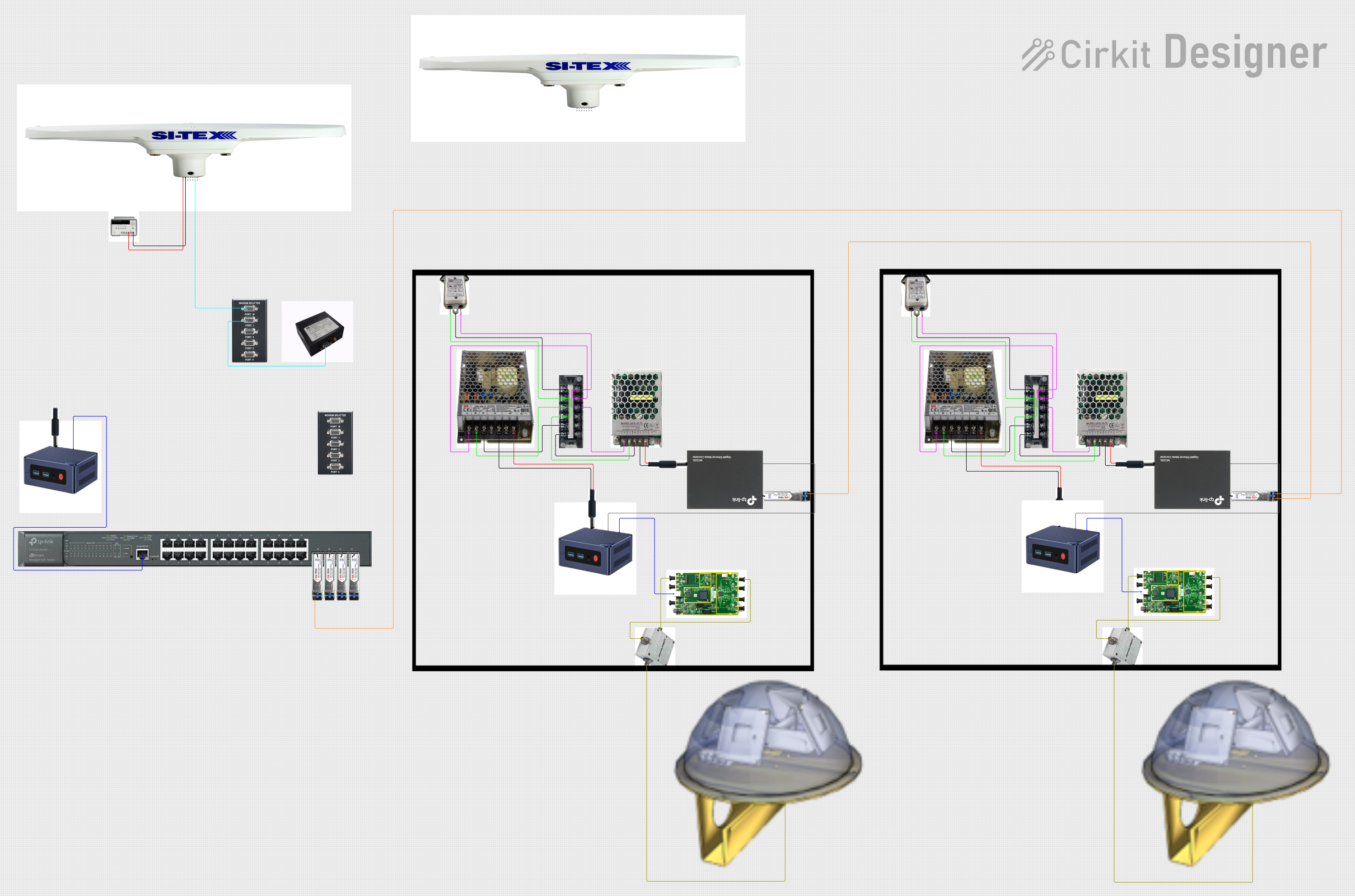
Satellite-Based Timing and Navigation System with SDR and Atomic Clock Synchronization
Image of GPS 시스템 측정 구성도_Confirm: A project utilizing RF Splitter in a practical application
This circuit appears to be a complex system involving power supply management, GPS and timing synchronization, and data communication. It includes a SI-TEX G1 Satellite Compass for GPS data, an XHTF1021 Atomic Rubidium Clock for precise timing, and Ettus USRP B200 units for software-defined radio communication. Power is supplied through various SMPS units and distributed via terminal blocks and DC jacks. Data communication is facilitated by Beelink MINI S12 N95 computers, RS232 splitters, and a 1000BASE-T Media Converter for network connectivity. RF Directional Couplers are used to interface antennas with the USRP units, and the entire system is likely contained within cases for protection and organization.
Cirkit Designer LogoOpen Project in Cirkit Designer
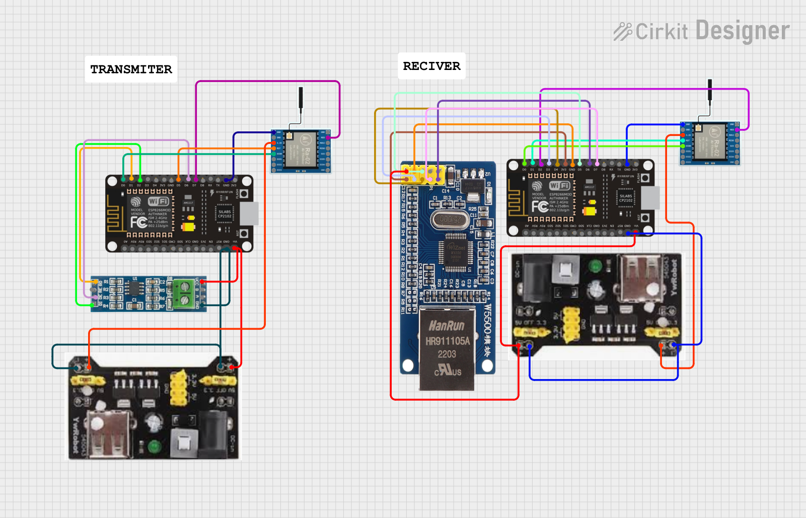
ESP8266 NodeMCU with LoRa and RS-485 Communication and Ethernet Connectivity
Image of Wiring Diagram LoRa: A project utilizing RF Splitter in a practical application
This circuit serves as a multi-protocol communication hub featuring two ESP8266 NodeMCUs for processing, each connected to a LoRa Ra-02 SX1278 for long-range wireless communication. One NodeMCU is also connected to an RS-485 module for serial communication and a W5500 Ethernet module for network connectivity, with MB102 modules supplying power.
Cirkit Designer LogoOpen Project in Cirkit Designer
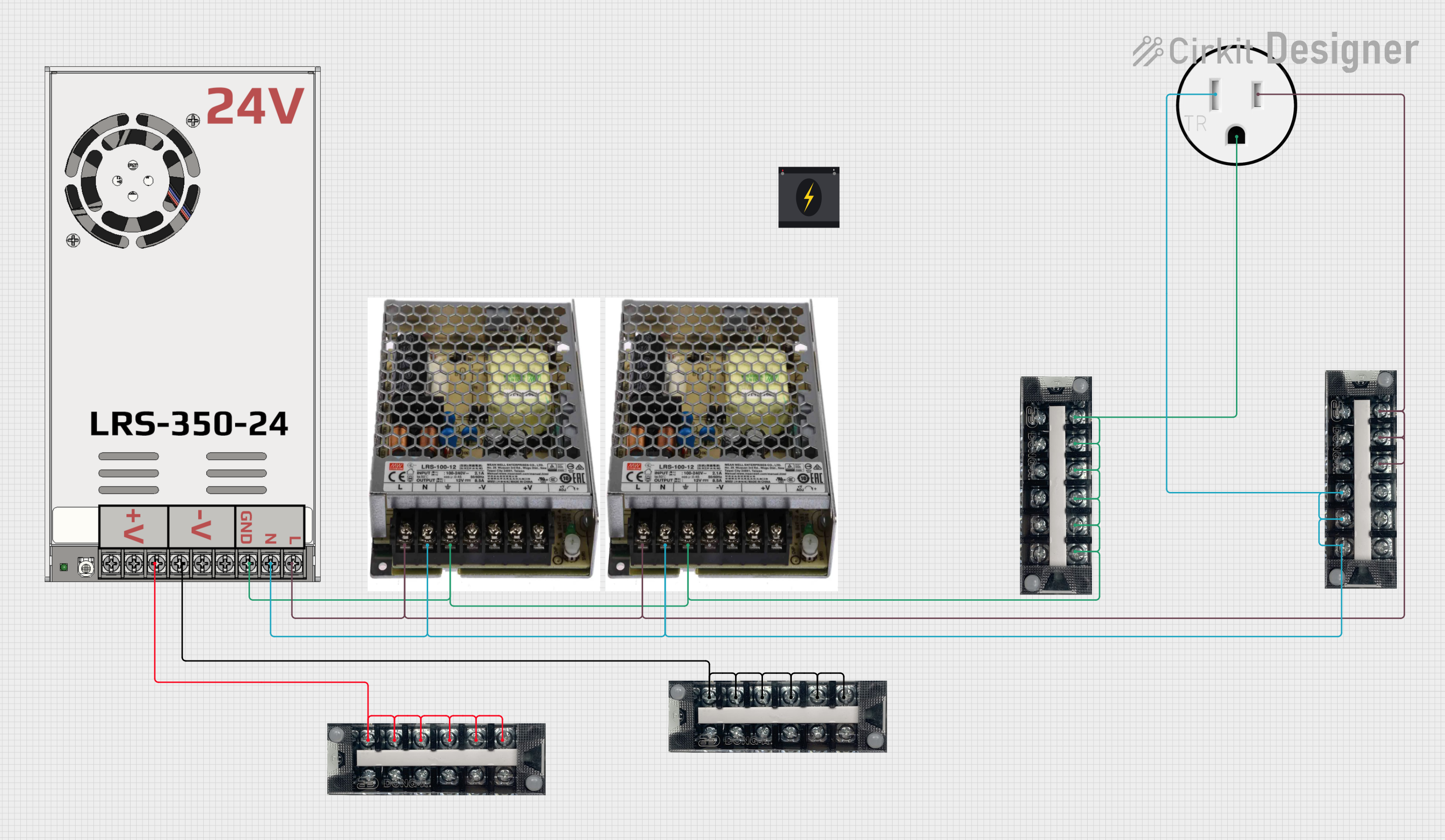
Modular Power Distribution System with Multiple SMPS Units and 120V Outlet
Image of Cellion-Tesla: A project utilizing RF Splitter in a practical application
This circuit is designed to convert 240V AC power to both 12V and 24V DC outputs using multiple SMPS units. Terminal blocks are used to organize and distribute the power, while a 120V outlet provides additional AC power access. The circuit is likely used for powering various electronic devices that require different voltage levels.
Cirkit Designer LogoOpen Project in Cirkit Designer

Explore Projects Built with RF Splitter

Use Cirkit Designer to design, explore, and prototype these projects online. Some projects support real-time simulation. Click "Open Project" to start designing instantly!
Image of GPS 시스템 측정 구성도_241016: A project utilizing RF Splitter in a practical application
Satellite Compass and Network-Integrated GPS Data Processing System
This circuit comprises a satellite compass, a mini PC, two GPS antennas, power supplies, a network switch, media converters, and an atomic rubidium clock. The satellite compass is powered by a triple output DC power supply and interfaces with an RS232 splitter for 1PPS signals. The mini PCs are connected to the USRP B200 devices via USB for data and power, and to media converters via Ethernet, which in turn connect to a network switch using fiber optic links. The antennas are connected to the USRP B200s through RF directional couplers, and the atomic clock provides a 1PPS input to the RS232 splitter.
Cirkit Designer LogoOpen Project in Cirkit Designer
Image of GPS 시스템 측정 구성도_Confirm: A project utilizing RF Splitter in a practical application
Satellite-Based Timing and Navigation System with SDR and Atomic Clock Synchronization
This circuit appears to be a complex system involving power supply management, GPS and timing synchronization, and data communication. It includes a SI-TEX G1 Satellite Compass for GPS data, an XHTF1021 Atomic Rubidium Clock for precise timing, and Ettus USRP B200 units for software-defined radio communication. Power is supplied through various SMPS units and distributed via terminal blocks and DC jacks. Data communication is facilitated by Beelink MINI S12 N95 computers, RS232 splitters, and a 1000BASE-T Media Converter for network connectivity. RF Directional Couplers are used to interface antennas with the USRP units, and the entire system is likely contained within cases for protection and organization.
Cirkit Designer LogoOpen Project in Cirkit Designer
Image of Wiring Diagram LoRa: A project utilizing RF Splitter in a practical application
ESP8266 NodeMCU with LoRa and RS-485 Communication and Ethernet Connectivity
This circuit serves as a multi-protocol communication hub featuring two ESP8266 NodeMCUs for processing, each connected to a LoRa Ra-02 SX1278 for long-range wireless communication. One NodeMCU is also connected to an RS-485 module for serial communication and a W5500 Ethernet module for network connectivity, with MB102 modules supplying power.
Cirkit Designer LogoOpen Project in Cirkit Designer
Image of Cellion-Tesla: A project utilizing RF Splitter in a practical application
Modular Power Distribution System with Multiple SMPS Units and 120V Outlet
This circuit is designed to convert 240V AC power to both 12V and 24V DC outputs using multiple SMPS units. Terminal blocks are used to organize and distribute the power, while a 120V outlet provides additional AC power access. The circuit is likely used for powering various electronic devices that require different voltage levels.
Cirkit Designer LogoOpen Project in Cirkit Designer

Technical Specifications

Key Technical Details

  • Frequency Range: Typically from 5 MHz to several GHz, depending on the model.
  • Impedance: Commonly 50 Ohms or 75 Ohms to match system impedance.
  • Insertion Loss: The loss of signal power resulting from the insertion of the splitter in the signal path.
  • Isolation: The degree to which the output ports are decoupled from one another.
  • VSWR (Voltage Standing Wave Ratio): A measure of impedance matching; a lower ratio indicates better matching.

Pin Configuration and Descriptions

Pin Number Description Notes
1 RF Input Connect to the RF signal source
2 RF Output 1 First divided signal output
3 RF Output 2 Second divided signal output
... ... Additional outputs as per model
N RF Output N N-th divided signal output

Note: The actual number of output pins depends on the model of the RF splitter.

Usage Instructions

How to Use the Component in a Circuit

  1. Connect the RF Source: Connect the RF signal source to the RF Input pin of the splitter.
  2. Connect the Outputs: Connect each RF Output pin to the intended receiver or subsequent component in the signal path.
  3. Power Considerations: As a passive device, the RF splitter does not require a power supply.

Important Considerations and Best Practices

  • Impedance Matching: Ensure that the impedance of the splitter matches the impedance of the system to minimize signal reflections.
  • Signal Loss: Be aware that each output will have a reduced signal level due to insertion loss.
  • Quality of Connectors: Use high-quality connectors and cables to minimize additional losses and maintain signal integrity.
  • Environment: Install the splitter in a location free from excessive moisture and temperature extremes to prevent damage.

Troubleshooting and FAQs

Common Issues

  • Signal Loss Greater Than Expected: This can be due to poor connections, impedance mismatch, or a defective splitter.
  • Interference or Poor Signal Quality: Ensure that the splitter is not located near devices that emit strong electromagnetic interference.

Solutions and Tips for Troubleshooting

  • Check Connections: Ensure all connections are secure and using the correct type of cable.
  • Impedance Matching: Verify that all components in the system have matched impedance.
  • Replace the Splitter: If the splitter is suspected to be faulty, replace it with a new one to see if the issue persists.

FAQs

Q: Can an RF splitter be used in reverse as a combiner? A: While theoretically possible, using an RF splitter as a combiner is not recommended as it may lead to poor performance and signal interference.

Q: Does the RF splitter introduce any delay in the signal? A: The RF splitter introduces a negligible delay, which is typically not a concern in most applications.

Q: Can I use a 75 Ohm splitter in a 50 Ohm system? A: It is not recommended as it will lead to impedance mismatch and increased VSWR, resulting in signal loss and potential damage to the system.

Example Code for Arduino UNO Connection

// Note: This example assumes the use of an RF module with an Arduino UNO
// and does not directly interface with the RF splitter. The RF splitter
// would be connected to the RF module's antenna output.

#include <SPI.h> // Include the SPI library for communication

void setup() {
  // Initialize serial communication for debugging purposes
  Serial.begin(9600);
  
  // Setup RF module communication here (SPI, I2C, etc.)
  // This will depend on the specific RF module being used.
}

void loop() {
  // Send a signal through the RF module
  // The RF splitter would then take this signal and split it accordingly.
  
  // Example: Transmitting a simple message
  String message = "Hello, World!";
  transmitRFSignal(message);
  
  // Add a delay between transmissions
  delay(1000);
}

void transmitRFSignal(String message) {
  // Code to transmit the RF signal through the connected RF module
  // This is a placeholder function and should be replaced with actual
  // transmission code specific to the RF module in use.
  
  Serial.println("Transmitting: " + message);
  // Add RF module-specific transmission code here
}

Note: The above code is a generic template and does not interact with the RF splitter directly. The RF splitter is a passive component and does not require software control. The code provided is for illustrative purposes to show how an RF signal might be generated from an Arduino before being split by the RF splitter.