How to Use FC F405 V4: Examples, Pinouts, and Specs
Introduction
The FC F405 V4 by SpeedyBee is a high-performance flight controller designed specifically for drones and multirotors. It is equipped with advanced processing capabilities, multiple input/output ports, and built-in sensors such as gyroscopes and accelerometers. These features enable precise stabilization, navigation, and support for various flight modes, making it an ideal choice for both hobbyists and professional drone enthusiasts.
Explore Projects Built with FC F405 V4


Explore Projects Built with FC F405 V4
Common Applications and Use Cases
- Multirotor Drones: Used for quadcopters, hexacopters, and other multirotor configurations.
- FPV Racing: Provides fast and accurate control for first-person-view racing drones.
- Aerial Photography: Ensures stable flight for capturing high-quality images and videos.
- Autonomous Navigation: Supports GPS and other modules for autonomous flight missions.
- Educational Projects: Ideal for learning about flight dynamics and drone programming.
Technical Specifications
Key Technical Details
- Processor: STM32F405 microcontroller
- IMU (Inertial Measurement Unit): Built-in gyroscope and accelerometer
- Input Voltage: 3S–6S LiPo battery (9V–30V)
- BEC Output: 5V/2A and 9V/2A
- UART Ports: 5 UARTs for peripherals (e.g., GPS, telemetry, receiver)
- ESC Signal Output: Supports up to 8 motor outputs
- OSD (On-Screen Display): Integrated Betaflight OSD
- Flash Memory: 16MB for blackbox logging
- Barometer: Built-in BMP280
- Dimensions: 36mm x 36mm (30.5mm x 30.5mm mounting holes)
- Weight: ~7g
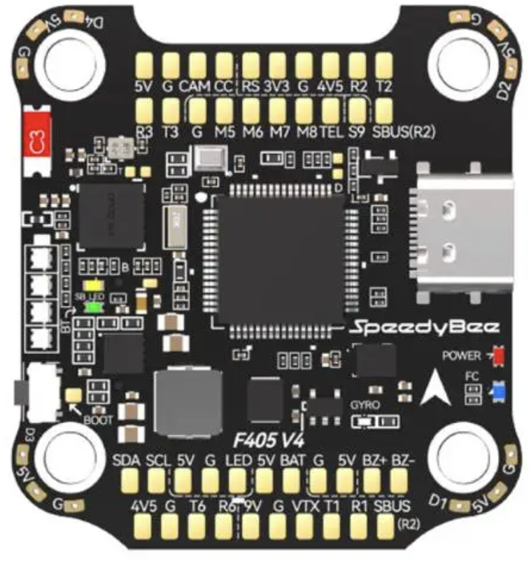
Pin Configuration and Descriptions
The FC F405 V4 features a variety of pins for connecting peripherals. Below is the pinout description:
| Pin Name | Description |
|---|---|
| GND | Ground connection for power and peripherals |
| VBAT | Voltage input for the flight controller (connect to battery) |
| 5V | 5V output for powering peripherals |
| 9V | 9V output for powering peripherals (e.g., VTX) |
| M1–M8 | Motor signal outputs for ESCs |
| RX1–RX5 | UART receive pins for peripherals (e.g., GPS, telemetry, receiver) |
| TX1–TX5 | UART transmit pins for peripherals |
| SCL/SDA | I2C interface for external sensors |
| LED | Addressable LED signal output |
| Buzzer | Buzzer signal output for audio alerts |
| RSSI | Analog input for receiver signal strength indication |
| Current | Analog input for current sensor |
| GND/Video In | Ground and video input for FPV camera |
| Video Out | Video output to VTX (with OSD overlay) |
Usage Instructions
How to Use the FC F405 V4 in a Circuit
Powering the Flight Controller:
- Connect the battery's positive terminal to the VBAT pin and the negative terminal to GND.
- Ensure the input voltage is within the supported range (9V–30V).
Connecting Motors and ESCs:
- Connect the signal wires from the ESCs to the M1–M8 pins.
- Ensure the ESCs are properly calibrated before flight.
Connecting Peripherals:
- Receiver: Use one of the UART ports (e.g., RX1/TX1) to connect your receiver.
- GPS: Connect the GPS module to an available UART port (e.g., RX2/TX2).
- FPV Camera and VTX: Connect the camera's video output to Video In and the VTX to Video Out.
Configuring the Flight Controller:
- Use Betaflight Configurator to flash firmware, configure settings, and calibrate sensors.
- Assign UART ports to specific peripherals in the Betaflight Ports tab.
Mounting:
- Secure the flight controller to the drone frame using the 30.5mm x 30.5mm mounting holes.
- Use vibration-dampening materials to reduce noise affecting the gyroscope.
Important Considerations and Best Practices
- Sensor Calibration: Always calibrate the gyroscope and accelerometer before the first flight.
- Firmware Updates: Regularly update the firmware using Betaflight Configurator to access new features and bug fixes.
- Power Supply: Ensure the power supply is stable and within the recommended voltage range.
- Blackbox Logging: Use the 16MB flash memory for blackbox logging to analyze flight performance and troubleshoot issues.
- Heat Management: Avoid overheating by ensuring proper airflow around the flight controller.
Example Code for Arduino UNO Integration
While the FC F405 V4 is not typically used with an Arduino UNO, you can use an Arduino to send commands or read telemetry data via UART. Below is an example of how to communicate with the flight controller:
#include <SoftwareSerial.h>

// Define RX and TX pins for SoftwareSerial
SoftwareSerial mySerial(10, 11); // RX = pin 10, TX = pin 11

void setup() {
  // Initialize serial communication
  Serial.begin(9600); // For debugging
  mySerial.begin(115200); // Communication with FC F405 V4

  Serial.println("Starting communication with FC F405 V4...");
}

void loop() {
  // Send a test command to the flight controller
  mySerial.println("Test Command");

  // Check for incoming data from the flight controller
  if (mySerial.available()) {
    String data = mySerial.readString();
    Serial.println("Received from FC: " + data);
  }

  delay(1000); // Wait 1 second before sending the next command
}
Troubleshooting and FAQs
Common Issues and Solutions
Flight Controller Not Powering On:
- Cause: Incorrect wiring or insufficient voltage.
- Solution: Verify the battery connection and ensure the input voltage is within 9V–30V.
No Response from Motors:
- Cause: ESCs not calibrated or incorrect motor mapping.
- Solution: Calibrate the ESCs and verify motor order in Betaflight.
Unstable Flight:
- Cause: Incorrect PID settings or uncalibrated sensors.
- Solution: Tune the PID settings in Betaflight and recalibrate the gyroscope and accelerometer.
No OSD Display:
- Cause: Incorrect wiring or OSD not enabled in Betaflight.
- Solution: Check the FPV camera and VTX connections, and enable OSD in Betaflight.
UART Ports Not Working:
- Cause: Incorrect port configuration.
- Solution: Assign the correct peripherals to UART ports in the Betaflight Ports tab.
FAQs
Q: Can I use a 2S battery with the FC F405 V4?
A: No, the minimum supported voltage is 9V, which corresponds to a 3S LiPo battery.Q: How do I update the firmware?
A: Use Betaflight Configurator to flash the latest firmware. Ensure the correct target is selected (e.g., SPEEDYBEE_F405).Q: Can I connect multiple peripherals to the same UART port?
A: No, each UART port should be dedicated to a single peripheral to avoid conflicts.Q: What is the purpose of the blackbox feature?
A: The blackbox logs flight data, which can be analyzed to troubleshoot issues or optimize performance.Q: Is the FC F405 V4 waterproof?
A: No, it is not waterproof. Use conformal coating to protect it from moisture if necessary.
This concludes the documentation for the SpeedyBee FC F405 V4 flight controller.