How to Use Pololu: Examples, Pinouts, and Specs
Introduction
Pololu is a company that designs and manufactures a wide range of electronic components, including motor controllers, sensors, and robotics products. These components are widely used in hobbyist, educational, and professional projects. Pololu products are known for their reliability, compact design, and ease of integration into various electronic systems.
Common applications of Pololu components include:
- Robotics and automation projects
- Motor control for DC, stepper, and servo motors
- Sensor integration for environmental monitoring
- Educational kits for learning electronics and programming
- Prototyping and DIY electronics projects
Explore Projects Built with Pololu


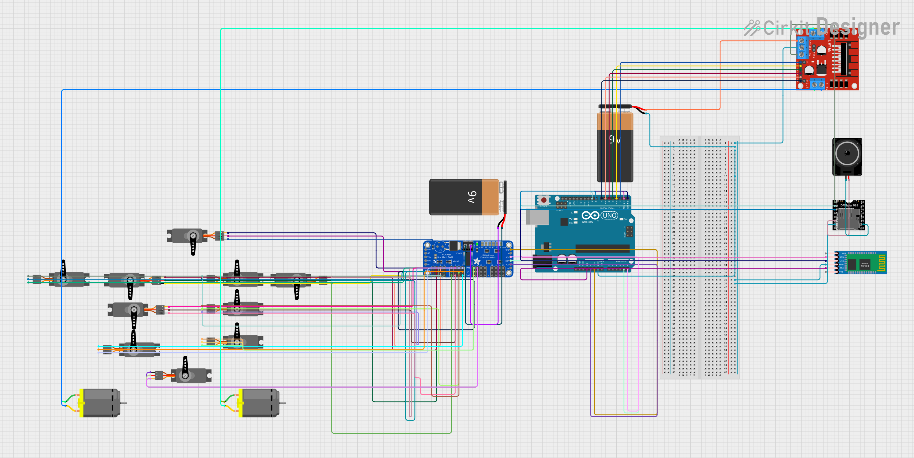
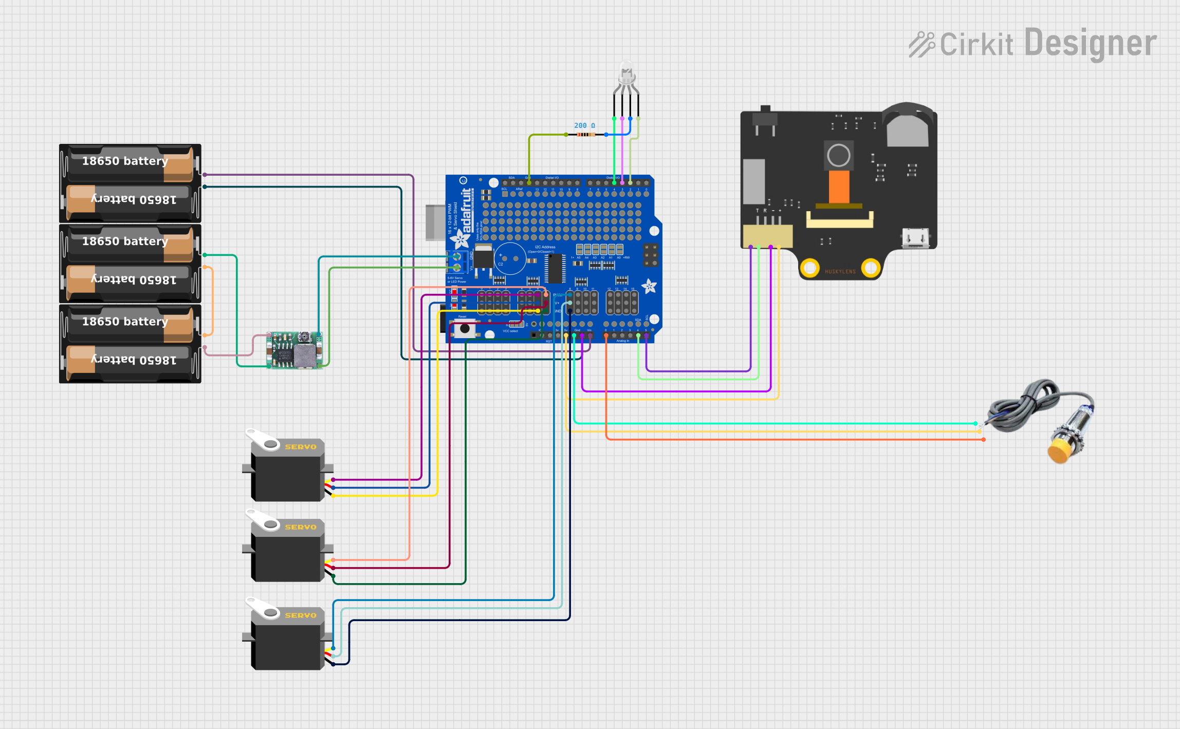
Explore Projects Built with Pololu
Technical Specifications
Pololu offers a variety of components, so the specifications vary depending on the product. Below is an example of a popular Pololu product: the Pololu DRV8835 Dual Motor Driver Carrier.
Key Technical Details
- Operating Voltage: 2.0 V to 11.0 V
- Continuous Output Current per Channel: 1.2 A
- Peak Output Current per Channel: 1.5 A (for short durations)
- Logic Voltage: 2.0 V to 7.0 V
- PWM Frequency: Up to 250 kHz
- Dimensions: 0.5" × 0.7" × 0.1" (13 mm × 18 mm × 3 mm)
- Weight: 0.5 g
Pin Configuration and Descriptions
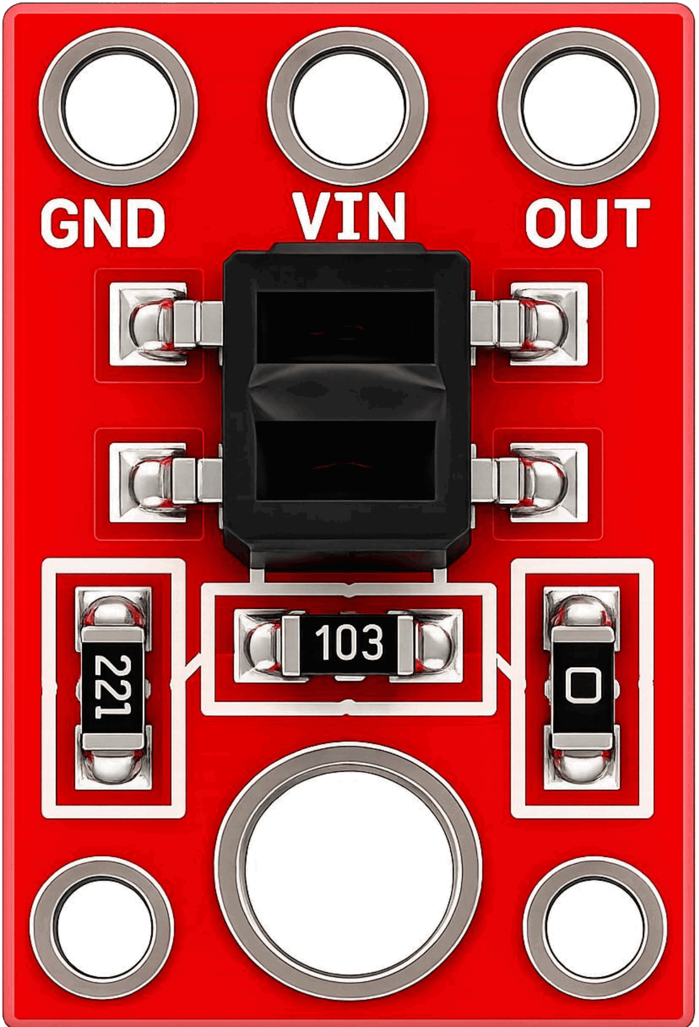
The Pololu DRV8835 Dual Motor Driver Carrier has the following pinout:
| Pin Name | Description |
|---|---|
| VIN | Motor power supply input (2.0 V to 11.0 V). |
| GND | Ground connection. |
| AIN1 | Control input for motor A (logic level). |
| AIN2 | Control input for motor A (logic level). |
| BIN1 | Control input for motor B (logic level). |
| BIN2 | Control input for motor B (logic level). |
| AO1 | Motor A output 1. |
| AO2 | Motor A output 2. |
| BO1 | Motor B output 1. |
| BO2 | Motor B output 2. |
| VCC | Logic voltage input (2.0 V to 7.0 V). |
| EN | Enable pin (active high, can be used to disable the driver). |
Usage Instructions
How to Use the Component in a Circuit
- Power Supply: Connect the VIN pin to a power source that matches the motor's voltage requirements (2.0 V to 11.0 V). Connect the GND pin to the ground of your circuit.
- Logic Voltage: Provide a logic voltage (2.0 V to 7.0 V) to the VCC pin. This voltage should match the logic level of your microcontroller.
- Motor Connections: Connect the motor terminals to the AO1/AO2 pins for motor A and BO1/BO2 pins for motor B.
- Control Inputs: Use the AIN1, AIN2, BIN1, and BIN2 pins to control the direction and speed of the motors. These pins accept PWM signals for speed control.
- Enable Pin: Optionally, connect the EN pin to a digital output of your microcontroller to enable or disable the driver.
Important Considerations and Best Practices
- Ensure that the power supply voltage matches the motor's specifications to avoid damage.
- Use appropriate heat dissipation methods if operating near the maximum current limits.
- Add decoupling capacitors near the VIN and VCC pins to reduce noise and improve stability.
- Avoid shorting the motor outputs (AO1/AO2 or BO1/BO2) as this can damage the driver.
Example Code for Arduino UNO
Below is an example code snippet to control two DC motors using the Pololu DRV8835 Dual Motor Driver Carrier:
// Define motor control pins
const int AIN1 = 3; // Motor A input 1
const int AIN2 = 5; // Motor A input 2
const int BIN1 = 6; // Motor B input 1
const int BIN2 = 9; // Motor B input 2

void setup() {
  // Set motor control pins as outputs
  pinMode(AIN1, OUTPUT);
  pinMode(AIN2, OUTPUT);
  pinMode(BIN1, OUTPUT);
  pinMode(BIN2, OUTPUT);
}

void loop() {
  // Example: Rotate Motor A forward and Motor B backward
  analogWrite(AIN1, 255); // Full speed forward for Motor A
  analogWrite(AIN2, 0);   // Stop reverse for Motor A
  analogWrite(BIN1, 0);   // Stop forward for Motor B
  analogWrite(BIN2, 255); // Full speed reverse for Motor B

  delay(2000); // Run for 2 seconds

  // Stop both motors
  analogWrite(AIN1, 0);
  analogWrite(AIN2, 0);
  analogWrite(BIN1, 0);
  analogWrite(BIN2, 0);

  delay(2000); // Pause for 2 seconds
}
Troubleshooting and FAQs
Common Issues
Motors Not Running:
- Verify that the power supply voltage is within the specified range.
- Check the connections to the motor and ensure they are secure.
- Ensure the control pins (AIN1, AIN2, BIN1, BIN2) are receiving the correct signals.
Overheating:
- Ensure the current draw of the motors does not exceed the driver's maximum rating.
- Use a heat sink or improve ventilation if the driver operates near its limits.
Erratic Motor Behavior:
- Check for noise in the power supply and add decoupling capacitors if necessary.
- Verify that the PWM frequency is within the driver's supported range.
FAQs
Q: Can I use this driver with a 3.3 V microcontroller?
A: Yes, the driver supports logic voltages as low as 2.0 V, making it compatible with 3.3 V systems.
Q: What happens if I reverse the motor power supply polarity?
A: Reversing the polarity can damage the driver. Always double-check your connections before powering the circuit.
Q: Can I control stepper motors with this driver?
A: No, the DRV8835 is designed for DC motors. For stepper motors, consider using a dedicated stepper motor driver like the Pololu A4988.
Q: How do I control motor speed?
A: Use PWM signals on the control pins (AIN1, AIN2, BIN1, BIN2) to adjust the motor speed. The duty cycle of the PWM signal determines the speed.