How to Use SGP40: Examples, Pinouts, and Specs
Introduction
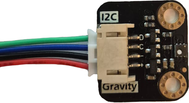
The SGP40 Air Quality Sensor V1.0 by DFRobot is a digital gas sensor designed for indoor air quality monitoring. It is capable of detecting a wide range of volatile organic compounds (VOCs) and provides a digital output proportional to the concentration of these gases. This makes it an ideal choice for applications such as smart home devices, air purifiers, HVAC systems, and air quality monitoring systems.
The SGP40 is based on Sensirion's advanced gas sensing technology, ensuring high accuracy, reliability, and long-term stability. Its compact design and I2C interface make it easy to integrate into various projects and systems.
Explore Projects Built with SGP40


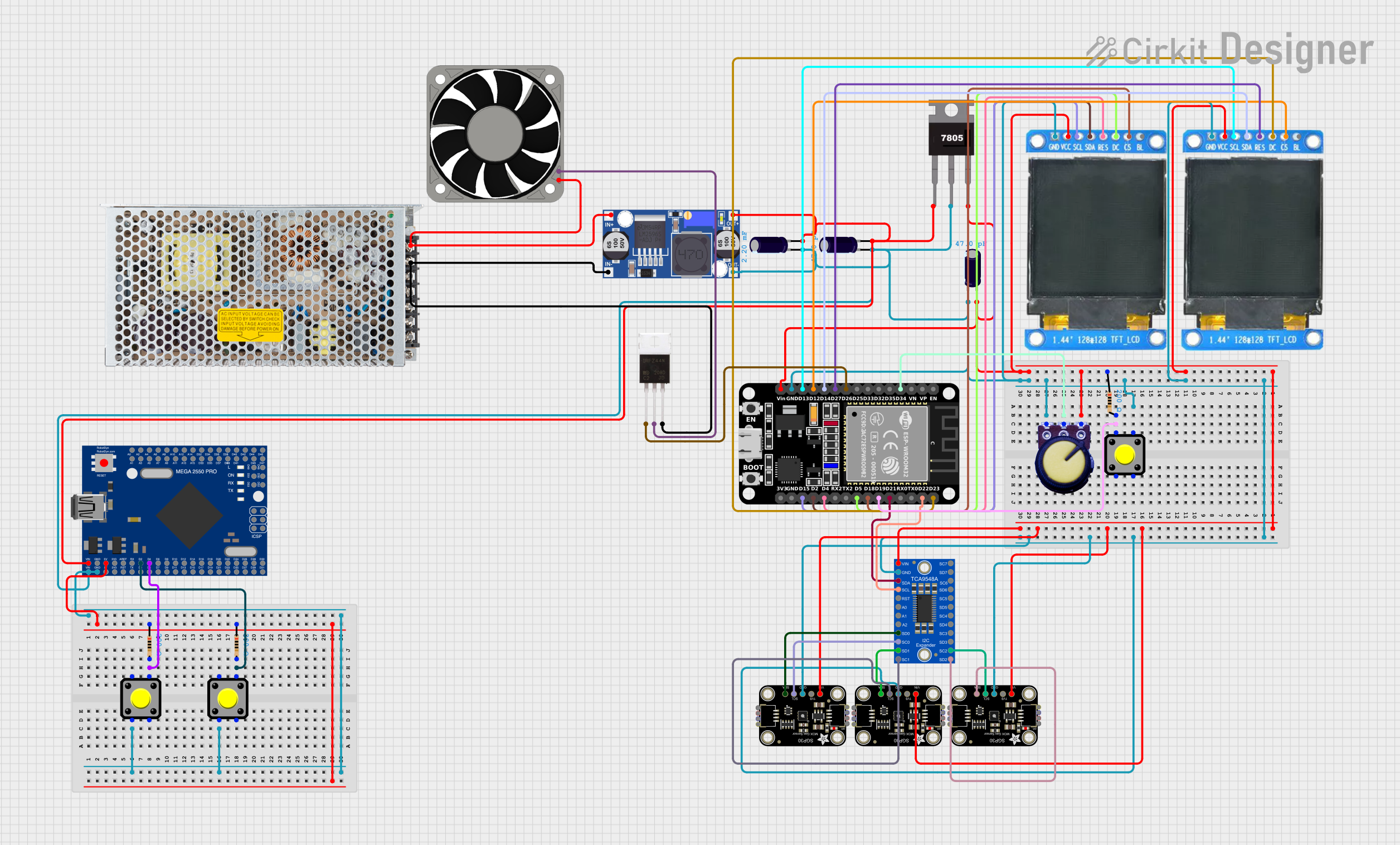

Explore Projects Built with SGP40
Technical Specifications
Below are the key technical details of the SGP40 Air Quality Sensor V1.0:
| Parameter | Value |
|---|---|
| Supply Voltage | 3.3V to 5V |
| Interface | I2C |
| Operating Current | ~2.6 mA |
| Measurement Range | 0 to 1,000 ppm (VOC Index) |
| Operating Temperature | -10°C to 50°C |
| Operating Humidity | 0% to 90% RH (non-condensing) |
| Dimensions | 22mm x 18mm |
Pin Configuration
The SGP40 sensor has a 4-pin interface. The pinout is as follows:
| Pin | Name | Description |
|---|---|---|
| 1 | VCC | Power supply (3.3V to 5V) |
| 2 | GND | Ground |
| 3 | SDA | I2C data line |
| 4 | SCL | I2C clock line |
Usage Instructions
How to Use the SGP40 in a Circuit
- Power Supply: Connect the VCC pin to a 3.3V or 5V power source and the GND pin to ground.
- I2C Communication: Connect the SDA and SCL pins to the corresponding I2C pins on your microcontroller (e.g., Arduino UNO).
- Pull-Up Resistors: Ensure that the I2C lines (SDA and SCL) have pull-up resistors (typically 4.7kΩ to 10kΩ) if they are not already present on your board.
- Initialization: Use the appropriate library or code to initialize the sensor and start reading VOC data.
Important Considerations and Best Practices
- Warm-Up Time: Allow the sensor to warm up for at least 10 seconds after powering it on for accurate readings.
- Ventilation: Ensure proper airflow around the sensor for reliable measurements.
- Avoid Contaminants: Keep the sensor away from dust, liquids, and other contaminants that could affect its performance.
- I2C Address: The default I2C address of the SGP40 is
0x59. Ensure no other devices on the I2C bus share this address.
Example Code for Arduino UNO
Below is an example of how to use the SGP40 with an Arduino UNO. This code uses the DFRobot SGP40 library, which can be installed via the Arduino Library Manager.
#include <Wire.h>
#include "DFRobot_SGP40.h"

// Create an SGP40 object
DFRobot_SGP40 sgp40;

void setup() {
  Serial.begin(9600); // Initialize serial communication
  Wire.begin();       // Initialize I2C communication

  // Initialize the SGP40 sensor
  if (!sgp40.begin()) {
    Serial.println("SGP40 initialization failed!");
    while (1); // Halt execution if initialization fails
  }
  Serial.println("SGP40 initialized successfully.");
}

void loop() {
  // Read the VOC index from the sensor
  uint16_t vocIndex = sgp40.getVOCIndex();

  // Print the VOC index to the serial monitor
  Serial.print("VOC Index: ");
  Serial.println(vocIndex);

  delay(1000); // Wait for 1 second before the next reading
}
Notes on the Code
- Ensure the DFRobot SGP40 library is installed before uploading the code.
- The
getVOCIndex()function retrieves the VOC index, which is a measure of air quality.
Troubleshooting and FAQs
Common Issues
Sensor Not Detected:
- Cause: Incorrect I2C wiring or address conflict.
- Solution: Verify the SDA and SCL connections and ensure no other devices share the
0x59address.
Inaccurate Readings:
- Cause: Insufficient warm-up time or poor ventilation.
- Solution: Allow the sensor to warm up for at least 10 seconds and ensure proper airflow.
Library Errors:
- Cause: Missing or outdated library.
- Solution: Install or update the DFRobot SGP40 library via the Arduino Library Manager.
FAQs
Q: Can the SGP40 detect specific gases?
A: The SGP40 is designed to measure a general VOC index rather than specific gases. It provides an overall indication of air quality.
Q: What is the lifespan of the SGP40 sensor?
A: The sensor is designed for long-term use with a typical lifespan of over 10 years under normal operating conditions.
Q: Can I use the SGP40 with a 3.3V microcontroller?
A: Yes, the SGP40 supports both 3.3V and 5V power supplies, making it compatible with a wide range of microcontrollers.
Q: Do I need to calibrate the sensor?
A: The SGP40 is factory-calibrated and does not require additional calibration for general use. However, for specific applications, you may need to adjust the readings based on environmental conditions.
By following this documentation, you can effectively integrate the SGP40 Air Quality Sensor V1.0 into your projects and ensure reliable performance.