How to Use DC 24V 25A 600W: Examples, Pinouts, and Specs
Introduction
The NUOFUWEI S-24-600 is a high-performance direct current (DC) power supply unit designed to deliver a stable 24V output with a maximum current of 25A, providing up to 600W of power. This power supply is ideal for powering high-current devices, industrial equipment, LED lighting systems, and other electronic circuits requiring a reliable DC power source.
Explore Projects Built with DC 24V 25A 600W


Explore Projects Built with DC 24V 25A 600W
Common Applications and Use Cases
- Industrial automation systems
- High-power LED lighting arrays
- CNC machines and 3D printers
- Motor drivers and robotics
- Laboratory testing and prototyping
- Battery charging systems
Technical Specifications
The following table outlines the key technical details of the NUOFUWEI S-24-600 power supply:
| Parameter | Specification |
|---|---|
| Input Voltage Range | 110V/220V AC (switchable) |
| Output Voltage | 24V DC |
| Maximum Output Current | 25A |
| Maximum Output Power | 600W |
| Efficiency | ≥85% |
| Operating Temperature | -10°C to +60°C |
| Cooling Method | Built-in fan (active cooling) |
| Dimensions | 215mm x 115mm x 50mm |
| Weight | ~1.2kg |
| Manufacturer Part ID | S-24-600 |
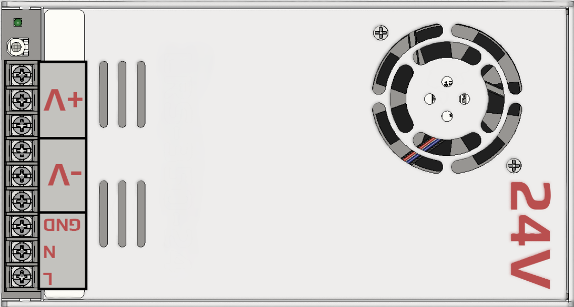
Pin Configuration and Descriptions
The NUOFUWEI S-24-600 features screw terminal connections for input and output. The pin configuration is as follows:
Input Terminals
| Pin | Label | Description |
|---|---|---|
| 1 | L | Live AC input (110V/220V) |
| 2 | N | Neutral AC input |
| 3 | GND | Earth ground |
Output Terminals
| Pin | Label | Description |
|---|---|---|
| 1 | V+ | Positive DC output (24V) |
| 2 | V+ | Positive DC output (24V) |
| 3 | V- | Negative DC output (Ground) |
| 4 | V- | Negative DC output (Ground) |
Adjustment
- Voltage Adjustment Knob: A small potentiometer near the output terminals allows fine-tuning of the output voltage (±10%).
Usage Instructions
How to Use the Component in a Circuit
Input Connection:
- Ensure the input voltage selector switch is set to the correct position (110V or 220V) based on your AC mains supply.
- Connect the live (L), neutral (N), and ground (GND) wires to the input terminals securely.
Output Connection:
- Connect the V+ and V- terminals to your load or circuit. Use appropriate gauge wires to handle the high current (25A max).
Voltage Adjustment:
- If necessary, use a small screwdriver to adjust the voltage potentiometer to fine-tune the output voltage.
Power On:
- After verifying all connections, power on the unit by supplying AC input. The built-in fan will activate to maintain optimal operating temperature.
Important Considerations and Best Practices
- Load Requirements: Ensure the connected load does not exceed the maximum power rating of 600W or the current limit of 25A.
- Ventilation: Install the power supply in a well-ventilated area to prevent overheating. Do not block the fan or ventilation holes.
- Safety: Always disconnect the power supply from the AC mains before making any wiring changes.
- Wire Gauge: Use wires rated for at least 25A for the output connections to avoid overheating or voltage drops.
- Fusing: Consider adding an external fuse or circuit breaker on the input side for additional protection.
Example: Connecting to an Arduino UNO
The NUOFUWEI S-24-600 can be used to power an Arduino UNO and other peripherals. Below is an example of how to connect the power supply to an Arduino UNO:
- Set the output voltage to 24V using the adjustment knob.
- Use a DC-DC step-down converter to reduce the 24V output to 5V for the Arduino UNO.
- Connect the step-down converter's input to the V+ and V- terminals of the power supply.
- Connect the step-down converter's 5V output to the Arduino UNO's 5V pin and GND.
Sample Arduino Code
// Example code to blink an LED connected to pin 13 of the Arduino UNO
// Ensure the Arduino is powered via the step-down converter (5V input).

void setup() {
  pinMode(13, OUTPUT); // Set pin 13 as an output
}

void loop() {
  digitalWrite(13, HIGH); // Turn the LED on
  delay(1000);            // Wait for 1 second
  digitalWrite(13, LOW);  // Turn the LED off
  delay(1000);            // Wait for 1 second
}
Troubleshooting and FAQs
Common Issues and Solutions
No Output Voltage:
- Verify that the input voltage selector switch is set correctly (110V or 220V).
- Check the AC input connections (L, N, and GND) for proper wiring.
- Ensure the load is connected securely to the output terminals.
Overheating:
- Ensure the power supply is installed in a well-ventilated area.
- Check for obstructions blocking the cooling fan or ventilation holes.
- Reduce the load if it exceeds the maximum power rating.
Voltage Fluctuations:
- Use the voltage adjustment knob to stabilize the output voltage.
- Verify that the input AC voltage is stable and within the specified range.
Fan Not Working:
- The fan operates based on temperature. If the unit is not hot, the fan may not activate.
- If the fan fails to operate under load, contact the manufacturer for support.
FAQs
Q1: Can I use this power supply to charge batteries?
A1: Yes, but ensure the battery charging voltage and current are within the power supply's specifications. Use a charge controller for optimal performance and safety.
Q2: Is the output voltage adjustable?
A2: Yes, the output voltage can be adjusted within ±10% of 24V using the built-in potentiometer.
Q3: Can I connect multiple devices to the output?
A3: Yes, as long as the total current draw does not exceed 25A and the total power does not exceed 600W.
Q4: Does the power supply have built-in protection?
A4: Yes, it includes overvoltage, overcurrent, and short-circuit protection.
For further assistance, refer to the manufacturer's documentation or contact NUOFUWEI support.