
How to Use 24V to 9V DCDC buck: Examples, Pinouts, and Specs
 Design with 24V to 9V DCDC buck in Cirkit Designer
Introduction
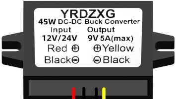
The 24V to 9V DC-DC buck converter is a power regulation module designed to step down a 24V input voltage to a stable 9V output voltage. This component is highly efficient, making it ideal for applications where energy conservation is critical. It is commonly used in battery-powered systems, industrial automation, automotive electronics, and embedded systems requiring a reliable 9V power source.
Explore Projects Built with 24V to 9V DCDC buck
 Open Project in Cirkit Designer
 Open Project in Cirkit Designer
 Open Project in Cirkit Designer
 Open Project in Cirkit Designer
Explore Projects Built with 24V to 9V DCDC buck
Open Project in Cirkit DesignerOpen Project in Cirkit DesignerOpen Project in Cirkit DesignerOpen Project in Cirkit DesignerCommon Applications:
- Powering 9V devices from a 24V power supply
- Voltage regulation in industrial control systems
- Automotive electronics for powering auxiliary devices
- Embedded systems and microcontroller projects
- LED lighting systems requiring a 9V supply
Technical Specifications
Below are the key technical details of the 24V to 9V DC-DC buck converter:
| Parameter | Value |
|---|---|
| Input Voltage Range | 18V to 26V |
| Output Voltage | 9V ± 0.1V |
| Maximum Output Current | 3A |
| Efficiency | Up to 95% |
| Switching Frequency | 150 kHz |
| Operating Temperature | -40°C to +85°C |
| Dimensions | 45mm x 25mm x 15mm |
Pin Configuration and Descriptions
The module typically has four pins or terminals for input and output connections:
| Pin Name | Description |
|---|---|
| VIN+ | Positive input voltage terminal (18V-26V) |
| VIN- | Negative input voltage terminal (GND) |
| VOUT+ | Positive output voltage terminal (9V) |
| VOUT- | Negative output voltage terminal (GND) |
Usage Instructions
How to Use the Component in a Circuit
Connect the Input Voltage:
- Connect the VIN+ pin to the positive terminal of your 24V power supply.
- Connect the VIN- pin to the ground (GND) of your power supply.
Connect the Output Voltage:
- Connect the VOUT+ pin to the positive terminal of the load requiring 9V.
- Connect the VOUT- pin to the ground (GND) of the load.
Verify Connections:
- Double-check all connections to ensure proper polarity and avoid short circuits.
Power On:
- Turn on the 24V power supply. The module will regulate the input voltage and provide a stable 9V output.
Important Considerations and Best Practices
- Input Voltage Range: Ensure the input voltage remains within the specified range (18V-26V) to prevent damage to the module.
- Heat Dissipation: For high current loads, the module may generate heat. Use a heatsink or ensure proper ventilation to maintain safe operating temperatures.
- Load Current: Do not exceed the maximum output current of 3A to avoid overloading the module.
- Polarity Protection: Double-check the polarity of input and output connections to prevent damage to the module or connected devices.
Example: Using with an Arduino UNO
The 24V to 9V DC-DC buck converter can be used to power an Arduino UNO, which operates at 5V but can accept a 9V input through its barrel jack. Below is an example circuit and Arduino code:
Circuit:
- Connect the VIN+ and VIN- pins of the buck converter to a 24V power supply.
- Connect the VOUT+ and VOUT- pins to the Arduino UNO's barrel jack (center pin is positive, outer sleeve is ground).
Arduino Code:
// Example code to blink an LED connected to pin 13
// Ensure the Arduino UNO is powered via the 9V output of the buck converter

void setup() {
  pinMode(13, OUTPUT); // Set pin 13 as an output
}

void loop() {
  digitalWrite(13, HIGH); // Turn the LED on
  delay(1000);            // Wait for 1 second
  digitalWrite(13, LOW);  // Turn the LED off
  delay(1000);            // Wait for 1 second
}
Troubleshooting and FAQs
Common Issues and Solutions
No Output Voltage:
- Cause: Incorrect input connections or insufficient input voltage.
- Solution: Verify the input voltage is within the 18V-26V range and check the polarity of the connections.
Overheating:
- Cause: High current load or poor ventilation.
- Solution: Reduce the load current or add a heatsink to the module.
Output Voltage Fluctuations:
- Cause: Unstable input voltage or excessive load.
- Solution: Ensure the input voltage is stable and the load does not exceed 3A.
Module Not Working After Connection:
- Cause: Reverse polarity or short circuit.
- Solution: Inspect the connections for errors and replace the module if damaged.
FAQs
Q: Can I use this module to power a 9V battery charger?
A: Yes, as long as the charger operates within the module's output current limit (3A).
Q: Is the module protected against reverse polarity?
A: Most modules do not include reverse polarity protection. Always double-check connections before powering on.
Q: Can I use this module with a 12V input?
A: No, the input voltage must be within the specified range of 18V-26V for proper operation.
Q: Does the module require additional capacitors?
A: The module typically includes onboard capacitors for filtering. However, you can add external capacitors for additional stability if needed.
This concludes the documentation for the 24V to 9V DC-DC buck converter.