How to Use BK-7670G TopSide: Examples, Pinouts, and Specs
Introduction
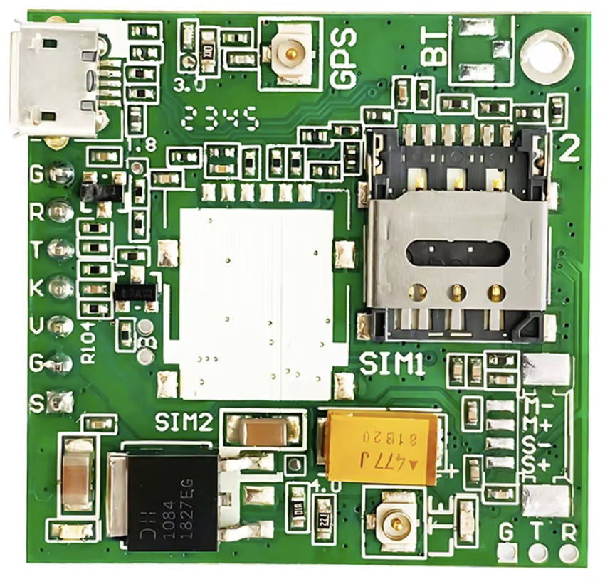
The BK-7670G TopSide is a high-performance circuit board developed by BK, designed to meet the demands of modern electronic applications. It features advanced connectivity options, robust signal integrity, and reliable operation, making it suitable for a wide range of use cases. This component is ideal for applications requiring high-speed data transfer, stable power distribution, and seamless integration with other electronic systems.
Explore Projects Built with BK-7670G TopSide


Explore Projects Built with BK-7670G TopSide
Common Applications and Use Cases
- Embedded systems and IoT devices
- High-speed data communication systems
- Industrial automation and control systems
- Prototyping and development of advanced circuits
- Signal processing and testing equipment
Technical Specifications
The BK-7670G TopSide is engineered to deliver exceptional performance. Below are its key technical details:
General Specifications
| Parameter | Value |
|---|---|
| Manufacturer | BK |
| Part ID | BK-7670 |
| Dimensions | 100mm x 80mm x 1.6mm |
| Operating Voltage Range | 3.3V to 5V |
| Maximum Current Rating | 2A |
| Operating Temperature | -40°C to 85°C |
| PCB Material | FR4 |
| Layer Count | 4 |
| Signal Integrity | High |
Pin Configuration and Descriptions
The BK-7670G TopSide features a versatile pin layout for easy integration into various systems. Below is the pin configuration:
| Pin Number | Pin Name | Description |
|---|---|---|
| 1 | VCC | Power supply input (3.3V to 5V) |
| 2 | GND | Ground connection |
| 3 | TX | Transmit data pin for serial communication |
| 4 | RX | Receive data pin for serial communication |
| 5 | SDA | I2C data line |
| 6 | SCL | I2C clock line |
| 7 | GPIO1 | General-purpose input/output pin 1 |
| 8 | GPIO2 | General-purpose input/output pin 2 |
| 9 | RESET | Reset pin for system initialization |
| 10 | NC | Not connected |
Usage Instructions
The BK-7670G TopSide is designed for ease of use in a variety of electronic projects. Follow the steps below to integrate it into your circuit:
Step 1: Powering the Board
- Connect the VCC pin to a stable power source within the range of 3.3V to 5V.
- Ensure the GND pin is connected to the ground of your circuit.
Step 2: Communication Setup
- For serial communication, connect the TX and RX pins to the corresponding pins on your microcontroller or device.
- For I2C communication, connect the SDA and SCL pins to the I2C bus of your system.
Step 3: GPIO Configuration
- Use the GPIO1 and GPIO2 pins for custom input/output operations. Configure these pins in your microcontroller's firmware as needed.
Step 4: Reset Functionality
- Connect the RESET pin to a push-button or control signal to reset the board when required.
Important Considerations
- Ensure the power supply voltage does not exceed 5V to avoid damaging the board.
- Use decoupling capacitors near the power pins to minimize noise and ensure stable operation.
- Avoid leaving unused pins floating; connect them to ground or configure them as needed.
Example: Connecting to an Arduino UNO
Below is an example of how to use the BK-7670G TopSide with an Arduino UNO for serial communication:
// Example: Serial communication with BK-7670G TopSide
// Connect TX (Pin 3) of BK-7670G to RX (Pin 0) of Arduino UNO
// Connect RX (Pin 4) of BK-7670G to TX (Pin 1) of Arduino UNO
// Ensure VCC and GND are properly connected

void setup() {
  Serial.begin(9600); // Initialize serial communication at 9600 baud
  delay(1000);        // Wait for the BK-7670G to initialize
  Serial.println("BK-7670G TopSide is ready!"); // Send a test message
}

void loop() {
  if (Serial.available()) {
    String data = Serial.readString(); // Read incoming data from BK-7670G
    Serial.print("Received: ");
    Serial.println(data); // Print the received data
  }
}
Troubleshooting and FAQs
Common Issues
No Power to the Board
- Cause: Incorrect voltage or loose connections.
- Solution: Verify that the power supply voltage is within the 3.3V to 5V range and that all connections are secure.
Communication Failure
- Cause: Incorrect wiring or mismatched baud rate.
- Solution: Double-check the TX and RX connections and ensure the baud rate in your code matches the BK-7670G's settings.
Unstable Operation
- Cause: Noise or insufficient power supply decoupling.
- Solution: Add decoupling capacitors (e.g., 0.1µF) near the power pins to stabilize the voltage.
FAQs
Q1: Can the BK-7670G TopSide operate at 3.3V?
A1: Yes, the board supports an operating voltage range of 3.3V to 5V.
Q2: What is the maximum data rate for serial communication?
A2: The BK-7670G supports serial communication at up to 115200 baud.
Q3: Are the GPIO pins configurable as analog inputs?
A3: No, the GPIO pins are digital-only and cannot be used as analog inputs.
Q4: Can I use the BK-7670G in outdoor environments?
A4: The board is rated for operation between -40°C and 85°C, but it must be protected from moisture and direct exposure to the elements.
By following this documentation, you can effectively integrate and utilize the BK-7670G TopSide in your electronic projects.