How to Use CAN BUS: Examples, Pinouts, and Specs
Introduction
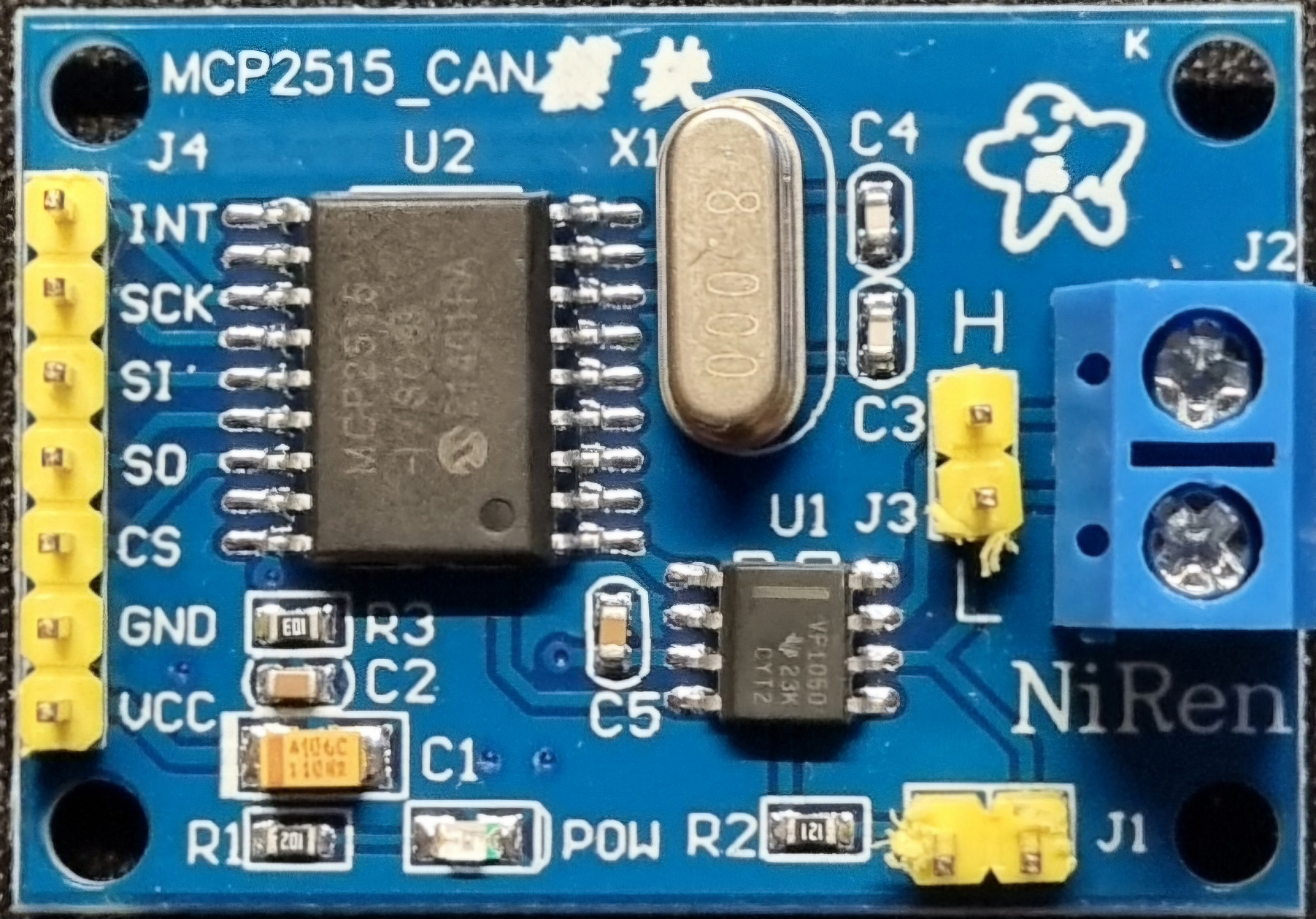
The CAN (Controller Area Network) BUS module is an electronic communication interface used for connecting multiple microcontrollers in applications without a host computer. It is commonly used in automotive and industrial systems for allowing microcontrollers and devices to communicate with each other within a vehicle or machinery without a central computer.
Explore Projects Built with CAN BUS
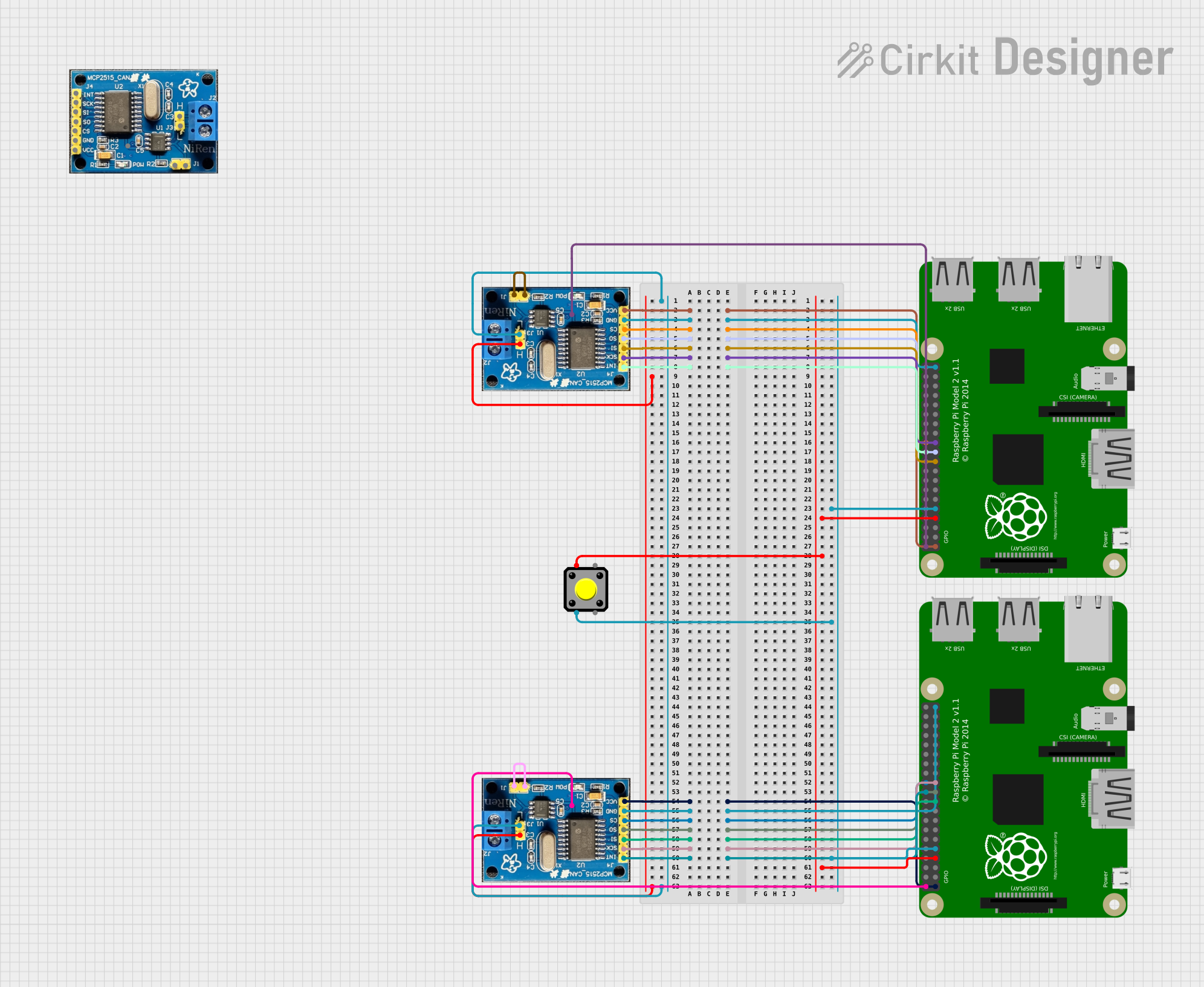
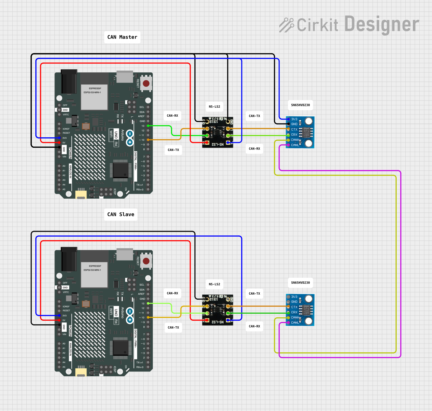
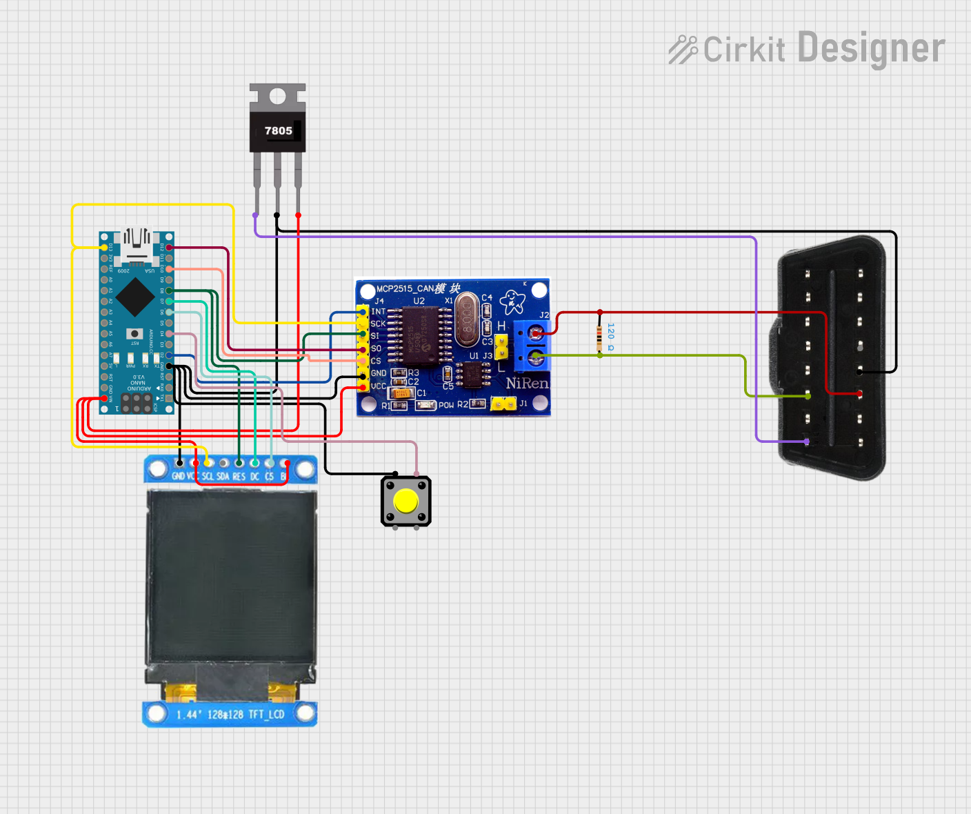

Explore Projects Built with CAN BUS
Common Applications and Use Cases
- Automotive systems (e.g., engine management, infotainment, sensors)
- Industrial automation and control systems
- Robotics
- Aerospace and defense systems
Technical Specifications
Key Technical Details
- Operating Voltage: Typically 5V
- Current Consumption: Varies with the module, often < 100 mA
- Differential Voltage Range: ±12V (max)
- Logic Level: 2.5V (recessive) to 3.5V (dominant)
- Maximum Speed: Up to 1 Mbps
Pin Configuration and Descriptions
| Pin Number | Name | Description |
|---|---|---|
| 1 | VCC | Power supply (5V) |
| 2 | GND | Ground connection |
| 3 | CANH | CAN High |
| 4 | CANL | CAN Low |
| 5 | RX | Receive data (optional, for some modules) |
| 6 | TX | Transmit data (optional, for some modules) |
Usage Instructions
How to Use the Component in a Circuit
- Power Connections: Connect the VCC pin to a 5V power supply and the GND pin to the ground.
- CAN Bus Connections: Connect the CANH and CANL pins to the corresponding CANH and CANL lines of the CAN network.
- Microcontroller Interface: If the module has RX and TX pins, connect them to the respective TX and RX pins of the microcontroller.
Important Considerations and Best Practices
- Ensure that the power supply is stable and within the specified voltage range.
- Terminate the CAN bus properly with 120-ohm resistors at both ends of the bus.
- Keep the CANH and CANL lines as twisted pairs to reduce interference.
- Avoid stubs in the CAN bus wiring to prevent signal reflections.
- Use shielded cables in noisy environments.
Example Code for Arduino UNO
#include <SPI.h>
#include <mcp_can.h>

// Initialize CAN BUS module with CS pin
MCP_CAN CAN(10);

void setup() {
  Serial.begin(115200);

  // Initialize CAN BUS module at 500kbps speed
  if (CAN_OK == CAN.begin(CAN_500KBPS)) {
    Serial.println("CAN BUS Shield init ok!");
  }
  else {
    Serial.println("CAN BUS Shield init fail");
    Serial.println("Init CAN BUS Shield again");
    delay(100);
  }
}

void loop() {
  // Check if data is available to read
  unsigned char len = 0;
  unsigned char buf[8];

  if (CAN_MSGAVAIL == CAN.checkReceive()) {
    CAN.readMsgBuf(&len, buf); // Read data,  len: data length, buf: data buffer
    unsigned long canId = CAN.getCanId();

    Serial.println("-----------------------------");
    Serial.print("Get data from ID: 0x");
    Serial.println(canId, HEX);

    for (int i = 0; i < len; i++) { // Print each byte of the data
      Serial.print(buf[i], HEX);
      Serial.print("\t");
    }
    Serial.println();
  }
}
Troubleshooting and FAQs
Common Issues Users Might Face
- No Communication: Check power supply, wiring, and termination resistors.
- Error Frames: Ensure there are no physical layer issues, such as damaged cables or connectors.
- Bus Off: The module may go into a bus-off state if errors exceed a certain threshold. Check for noise, incorrect baud rate, or faulty nodes.
Solutions and Tips for Troubleshooting
- Verify that all connections are secure and correct.
- Use an oscilloscope to check the signal quality on the CANH and CANL lines.
- Ensure that all nodes on the network have a unique identifier.
- Check for software issues, such as incorrect initialization of the CAN module.
FAQs
Q: Can I use the CAN BUS module with a 3.3V system? A: Some CAN BUS modules are 3.3V compatible, but you must check the specific module's datasheet.
Q: How many devices can be connected to a CAN BUS? A: The CAN specification allows up to 112 nodes, but practical limits are lower and depend on the total bus length and the transceiver used.
Q: What is the maximum length of a CAN BUS network? A: The maximum length depends on the baud rate; for example, at 1 Mbps, the maximum length is typically around 40 meters.
Q: Do I need to use termination resistors? A: Yes, proper termination is critical for preventing reflections and ensuring signal integrity on the CAN bus.