
How to Use POWER SUPPLY 24V: Examples, Pinouts, and Specs
 Design with POWER SUPPLY 24V in Cirkit Designer
Introduction
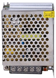
The POWER SUPPLY 24V is a device that converts electrical energy from an input source (such as AC mains or DC power) into a stable 24V DC output. It is widely used to power electronic circuits, industrial equipment, and automation systems. This component ensures a reliable and consistent voltage supply, which is critical for the proper functioning of sensitive electronic devices.
Explore Projects Built with POWER SUPPLY 24V
 Open Project in Cirkit Designer
 Open Project in Cirkit Designer
 Open Project in Cirkit Designer
 Open Project in Cirkit Designer
Explore Projects Built with POWER SUPPLY 24V
Open Project in Cirkit DesignerOpen Project in Cirkit DesignerOpen Project in Cirkit DesignerOpen Project in Cirkit DesignerCommon Applications and Use Cases
- Powering industrial control systems and PLCs (Programmable Logic Controllers)
- Supplying voltage to sensors, actuators, and relays
- Driving LED lighting systems
- Providing power to motor drivers and robotics
- General-purpose use in laboratory and prototyping environments
Technical Specifications
Below are the key technical details of the POWER SUPPLY 24V:
| Parameter | Specification |
|---|---|
| Input Voltage Range | 100-240V AC (typical) or 12-48V DC |
| Output Voltage | 24V DC ± 1% |
| Output Current | 1A to 10A (varies by model) |
| Power Rating | 24W to 240W (depending on model) |
| Efficiency | ≥ 85% |
| Ripple and Noise | ≤ 50mV |
| Operating Temperature | -20°C to +70°C |
| Protection Features | Overvoltage, Overcurrent, Short Circuit |
| Mounting Options | DIN rail, panel mount, or standalone |
Pin Configuration and Descriptions
The POWER SUPPLY 24V typically has the following input and output terminals:
| Pin/Terminal | Label | Description |
|---|---|---|
| 1 | L | AC Live input (for AC-powered models) |
| 2 | N | AC Neutral input (for AC-powered models) |
| 3 | GND | Ground/Earth connection |
| 4 | +V | Positive 24V DC output |
| 5 | -V | Negative 24V DC output (ground reference) |
For DC-powered models, the input terminals may be labeled as +Vin and -Vin instead of L and N.
Usage Instructions
How to Use the POWER SUPPLY 24V in a Circuit
Input Connection:
- For AC-powered models, connect the
LandNterminals to the AC mains supply. Ensure the input voltage is within the specified range (e.g., 100-240V AC). - For DC-powered models, connect the
+Vinand-Vinterminals to a DC power source within the specified range (e.g., 12-48V DC).
- For AC-powered models, connect the
Output Connection:
- Connect the
+Vterminal to the positive rail of your circuit. - Connect the
-Vterminal to the ground rail of your circuit.
- Connect the
Grounding:
- For safety, connect the
GNDterminal to the earth ground.
- For safety, connect the
Load Considerations:
- Ensure the total current drawn by the connected devices does not exceed the maximum output current rating of the power supply.
Power On:
- After verifying all connections, power on the input source. The power supply will provide a stable 24V DC output.
Important Considerations and Best Practices
- Ventilation: Ensure adequate airflow around the power supply to prevent overheating.
- Load Regulation: Avoid sudden changes in load that exceed the power supply's transient response capability.
- Protection Features: The power supply includes built-in protections (e.g., overvoltage, overcurrent). If triggered, disconnect the load, resolve the issue, and restart the power supply.
- Polarity: Double-check the polarity of connections to avoid damage to the power supply or connected devices.
Example: Using the POWER SUPPLY 24V with an Arduino UNO
The POWER SUPPLY 24V can be used to power devices connected to an Arduino UNO. However, since the Arduino operates at 5V, a step-down voltage regulator (e.g., LM7805 or a DC-DC buck converter) is required.
Circuit Diagram
- Connect the
+Vterminal of the power supply to the input of the voltage regulator. - Connect the output of the voltage regulator to the Arduino's
5Vpin. - Connect the
-Vterminal of the power supply to the Arduino'sGNDpin.
Sample Code
// Example code to blink an LED connected to Arduino UNO
// Ensure the Arduino is powered via the 5V pin from the step-down regulator

const int ledPin = 13; // Built-in LED pin on Arduino UNO

void setup() {
  pinMode(ledPin, OUTPUT); // Set LED pin as output
}

void loop() {
  digitalWrite(ledPin, HIGH); // Turn the LED on
  delay(1000);               // Wait for 1 second
  digitalWrite(ledPin, LOW);  // Turn the LED off
  delay(1000);               // Wait for 1 second
}
Troubleshooting and FAQs
Common Issues and Solutions
No Output Voltage:
- Cause: Input power is not connected or is outside the specified range.
- Solution: Verify the input connections and ensure the input voltage is within the acceptable range.
Overheating:
- Cause: Insufficient ventilation or excessive load.
- Solution: Ensure proper airflow around the power supply and reduce the load to within the rated current.
Output Voltage Fluctuations:
- Cause: Load exceeds the power supply's capacity or input voltage is unstable.
- Solution: Reduce the load or stabilize the input voltage.
Protection Features Triggered:
- Cause: Overvoltage, overcurrent, or short circuit.
- Solution: Disconnect the load, resolve the issue, and restart the power supply.
FAQs
Q1: Can I use the POWER SUPPLY 24V to charge a 24V battery?
A1: No, this power supply is not designed for battery charging. Use a dedicated battery charger with appropriate charging profiles.
Q2: Is the POWER SUPPLY 24V suitable for outdoor use?
A2: Most models are designed for indoor use. If outdoor use is required, ensure the power supply has an appropriate IP rating for weather resistance.
Q3: Can I connect multiple power supplies in parallel to increase current?
A3: Only if the power supplies are specifically designed for parallel operation. Otherwise, this may cause instability or damage.
Q4: What happens if I connect the output terminals in reverse polarity?
A4: Reverse polarity can damage the connected devices. Always double-check the polarity before powering on the system.