
How to Use KA78R05 Low Dropout Voltage Regulator: Examples, Pinouts, and Specs
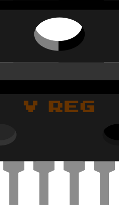
 Design with KA78R05 Low Dropout Voltage Regulator in Cirkit Designer
Introduction
The KA78R05, manufactured by Fairchild, is a low dropout voltage regulator designed to provide a stable 5V output. It is particularly suited for applications requiring efficient voltage regulation with minimal input-output voltage difference. The KA78R05 is equipped with built-in thermal overload protection and short-circuit protection, ensuring safe and reliable operation under various conditions.
Explore Projects Built with KA78R05 Low Dropout Voltage Regulator
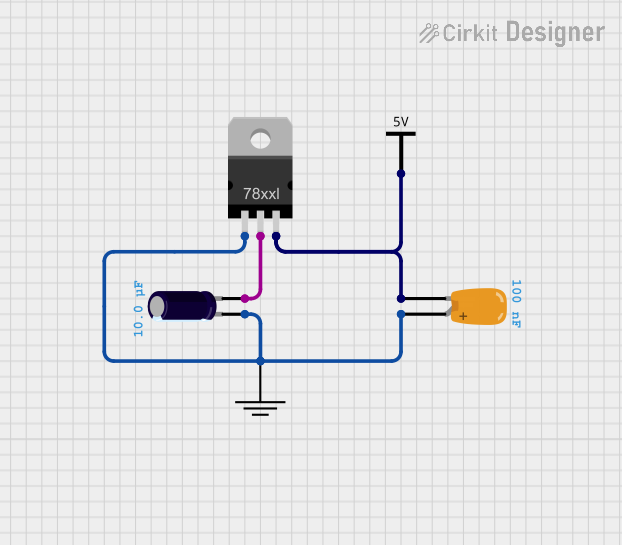 Open Project in Cirkit Designer
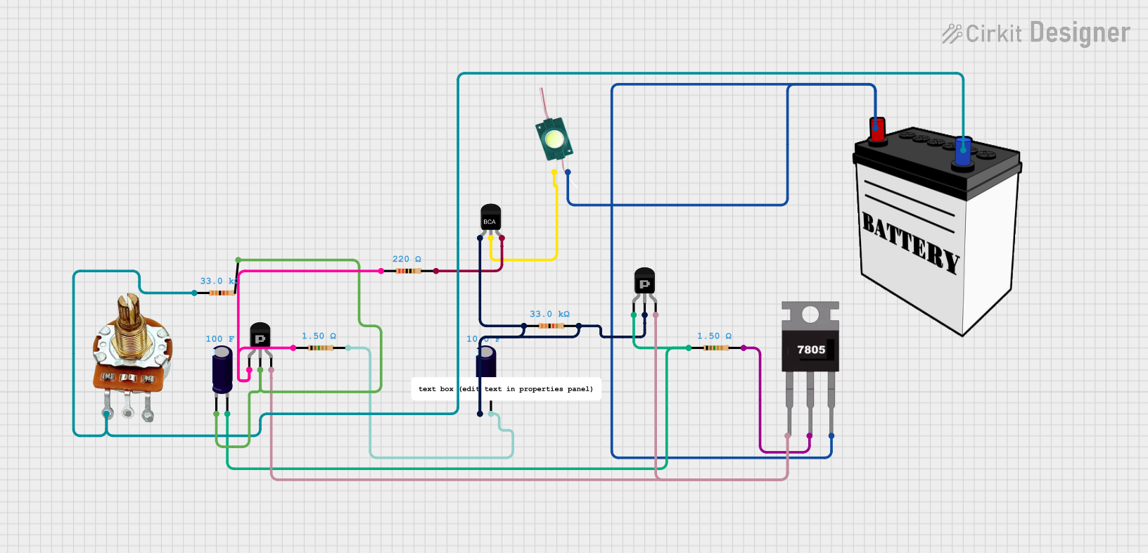 Open Project in Cirkit Designer
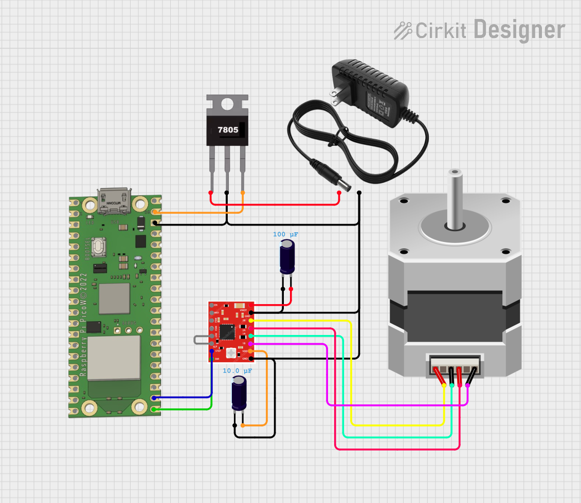 Open Project in Cirkit Designer
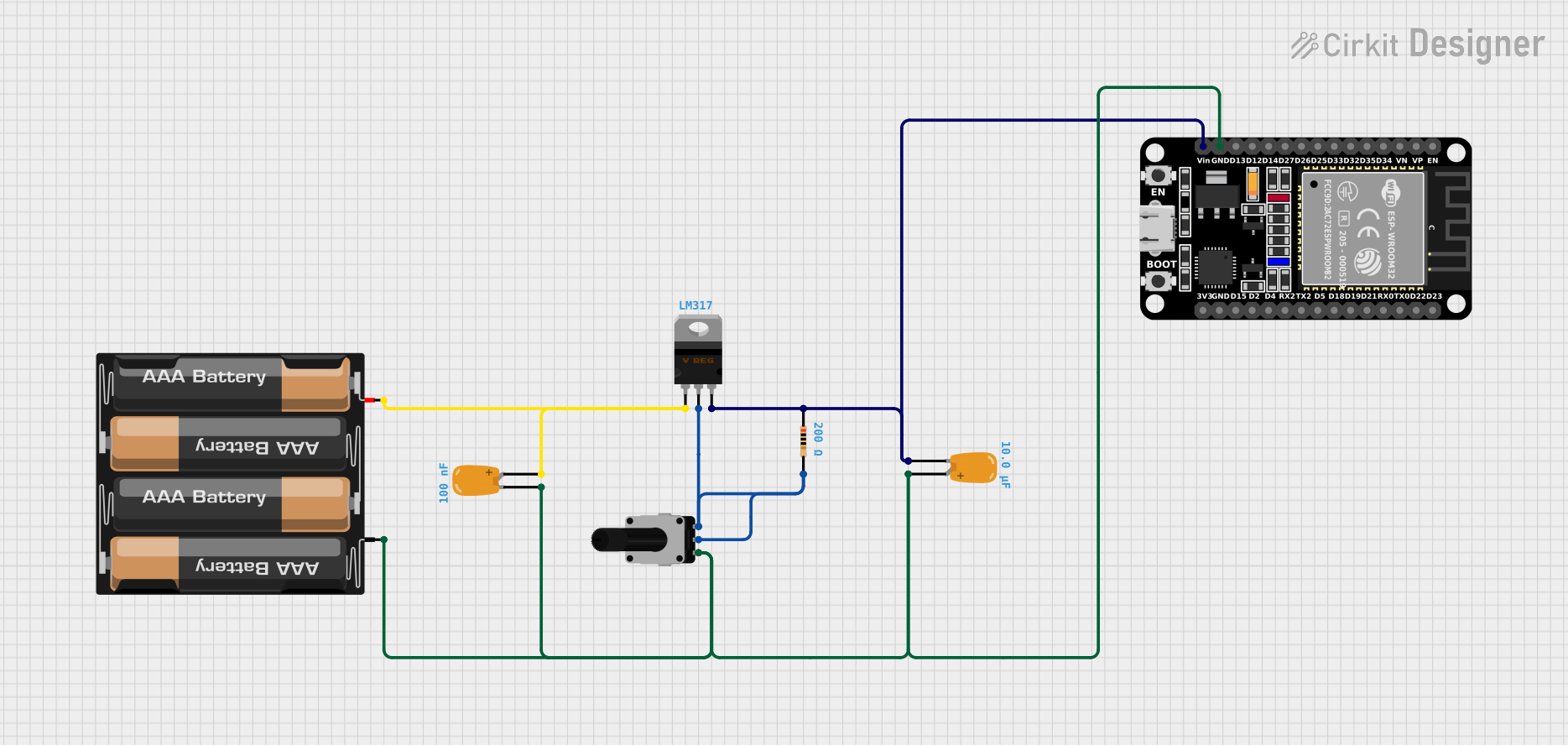 Open Project in Cirkit Designer
Explore Projects Built with KA78R05 Low Dropout Voltage Regulator
Open Project in Cirkit DesignerOpen Project in Cirkit DesignerOpen Project in Cirkit DesignerOpen Project in Cirkit DesignerCommon Applications
- Battery-powered devices
- Microcontroller-based systems
- Consumer electronics
- Industrial control systems
- Power supply circuits
Technical Specifications
Key Specifications
| Parameter | Value |
|---|---|
| Output Voltage | 5V |
| Input Voltage Range | 7V to 25V |
| Dropout Voltage | 0.5V (typical) |
| Maximum Output Current | 1A |
| Quiescent Current | 5mA (typical) |
| Operating Temperature Range | -40°C to +125°C |
| Protection Features | Thermal overload, short-circuit |
Pin Configuration and Descriptions
The KA78R05 is available in a TO-220 package with three pins. The pin configuration is as follows:
| Pin Number | Pin Name | Description |
|---|---|---|
| 1 | Input | Voltage input (7V to 25V) |
| 2 | Ground | Ground reference |
| 3 | Output | Regulated 5V output |
Usage Instructions
How to Use the KA78R05 in a Circuit
- Input Voltage: Connect a DC voltage source (7V to 25V) to the input pin. Ensure the input voltage is at least 2V higher than the desired 5V output for proper regulation.
- Output Voltage: Connect the load to the output pin. The KA78R05 will provide a stable 5V output.
- Ground Connection: Connect the ground pin to the circuit's ground.
- Capacitors: For stable operation, use the following capacitors:
- A 0.33µF ceramic capacitor between the input pin and ground.
- A 0.1µF ceramic capacitor between the output pin and ground.
Important Considerations
- Heat Dissipation: If the regulator operates at high currents or with a large input-output voltage difference, it may generate heat. Use a heatsink with the TO-220 package to prevent overheating.
- Protection Features: The KA78R05 includes thermal overload and short-circuit protection. However, avoid prolonged exposure to extreme conditions to ensure longevity.
- Input Voltage Range: Do not exceed the maximum input voltage of 25V to prevent damage to the regulator.
Example: Using KA78R05 with an Arduino UNO
The KA78R05 can be used to power an Arduino UNO by providing a stable 5V supply. Below is an example circuit and Arduino code:
Circuit Setup
- Connect a 9V battery to the input pin of the KA78R05.
- Connect the output pin of the KA78R05 to the 5V pin of the Arduino UNO.
- Connect the ground pin of the KA78R05 to the GND pin of the Arduino UNO.
Arduino Code
// Example code to blink an LED using Arduino UNO powered by KA78R05
const int ledPin = 13; // Pin connected to the onboard LED

void setup() {
  pinMode(ledPin, OUTPUT); // Set the LED pin as an output
}

void loop() {
  digitalWrite(ledPin, HIGH); // Turn the LED on
  delay(1000); // Wait for 1 second
  digitalWrite(ledPin, LOW); // Turn the LED off
  delay(1000); // Wait for 1 second
}
Troubleshooting and FAQs
Common Issues and Solutions
No Output Voltage:
- Ensure the input voltage is within the specified range (7V to 25V).
- Check the connections for loose wires or incorrect pin assignments.
- Verify that the input and output capacitors are properly connected.
Overheating:
- Use a heatsink to dissipate heat if the regulator becomes too hot.
- Reduce the input voltage to minimize the input-output voltage difference.
Output Voltage Fluctuations:
- Ensure the capacitors on the input and output pins are of the correct value and type.
- Check for excessive load current exceeding the 1A maximum rating.
Short Circuit Protection Triggered:
- Disconnect the load and inspect for short circuits in the circuit.
- Verify that the load current does not exceed the regulator's capacity.
FAQs
Q1: Can I use the KA78R05 to power a 3.3V device?
A1: No, the KA78R05 provides a fixed 5V output. To power a 3.3V device, use a step-down regulator or a 3.3V LDO.
Q2: What happens if the input voltage drops below 7V?
A2: The regulator may fail to maintain a stable 5V output, leading to voltage drops or instability.
Q3: Can I use the KA78R05 without capacitors?
A3: No, capacitors are essential for stable operation and to prevent oscillations. Always use the recommended capacitor values.
Q4: Is the KA78R05 suitable for automotive applications?
A4: Yes, as long as the input voltage remains within the specified range and proper heat dissipation is ensured.