How to Use ESP8266: Examples, Pinouts, and Specs
Introduction
The ESP8266, manufactured by ESP8266, is a low-cost Wi-Fi microchip with a full TCP/IP stack and microcontroller capability. It is widely used in Internet of Things (IoT) applications due to its affordability, ease of use, and robust feature set. The ESP8266 can operate as both a standalone microcontroller or as a Wi-Fi module for other microcontrollers, making it a versatile choice for a variety of projects.
Explore Projects Built with ESP8266
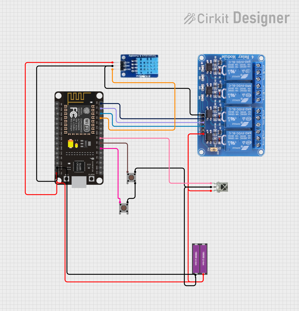

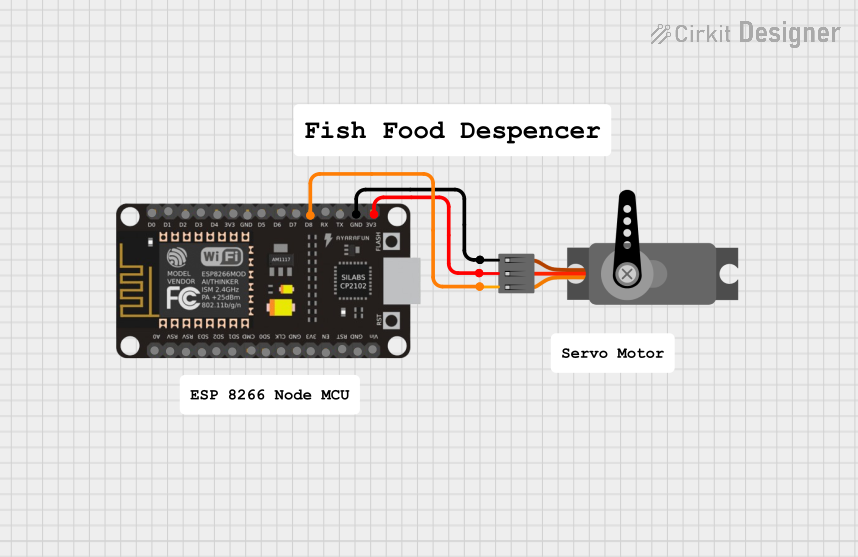

Explore Projects Built with ESP8266
Common Applications and Use Cases
- Home automation systems
- Smart appliances
- Wireless sensor networks
- IoT prototyping and development
- Remote data logging and monitoring
- Wi-Fi-enabled robotics
Technical Specifications
The ESP8266 is a highly integrated chip with the following key specifications:
| Parameter | Value |
|---|---|
| Microcontroller | 32-bit Tensilica L106 running at 80 MHz (can be overclocked to 160 MHz) |
| Flash Memory | 512 KB to 4 MB (varies by module) |
| RAM | 64 KB instruction RAM, 96 KB data RAM |
| Wi-Fi Standards | 802.11 b/g/n (2.4 GHz) |
| Operating Voltage | 3.0V to 3.6V |
| GPIO Pins | Up to 17 GPIOs (depending on the module) |
| Communication Interfaces | UART, SPI, I2C, I2S, PWM, ADC |
| ADC Resolution | 10-bit |
| Power Consumption | 15 µA (deep sleep), 70 mA (active average) |
| Operating Temperature | -40°C to +125°C |
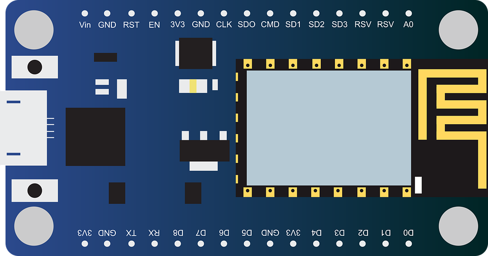
Pin Configuration and Descriptions
The ESP8266 is available in various module formats, such as the ESP-01, ESP-12E, and NodeMCU. Below is the pinout for the ESP-12E module, one of the most commonly used variants:
| Pin Name | Pin Number | Description |
|---|---|---|
| VCC | 1 | Power supply (3.3V). Do not exceed 3.6V. |
| GND | 2 | Ground connection. |
| TX | 3 | UART Transmit pin. Used for serial communication. |
| RX | 4 | UART Receive pin. Used for serial communication. |
| GPIO0 | 5 | General-purpose I/O pin. Used for boot mode selection during startup. |
| GPIO2 | 6 | General-purpose I/O pin. |
| GPIO15 | 7 | General-purpose I/O pin. Must be pulled LOW during boot. |
| EN (CH_PD) | 8 | Chip enable. Must be HIGH for normal operation. |
| RST | 9 | Reset pin. Active LOW. |
| ADC (A0) | 10 | Analog-to-digital converter input (0–1V). |
Note: The exact pinout may vary depending on the ESP8266 module you are using. Always refer to the datasheet for your specific module.
Usage Instructions
How to Use the ESP8266 in a Circuit
- Power Supply: Provide a stable 3.3V power supply to the VCC pin. Avoid exceeding 3.6V to prevent damage.
- Boot Mode Selection:
- Pull GPIO0 LOW and GPIO15 LOW to enter programming mode.
- Pull GPIO0 HIGH and GPIO15 LOW for normal operation.
- Serial Communication: Connect the TX and RX pins to a USB-to-serial adapter or a microcontroller for programming and communication.
- Pull-Up/Pull-Down Resistors: Use appropriate pull-up or pull-down resistors on GPIO0, GPIO2, and GPIO15 to ensure proper boot mode selection.
- Reset and Enable: Connect the RST and EN pins to push buttons or microcontroller pins for manual reset and enable control.
Important Considerations and Best Practices
- Voltage Levels: The ESP8266 operates at 3.3V logic levels. Use a level shifter if interfacing with 5V devices.
- Power Supply: Ensure your power supply can provide at least 300 mA of current to handle Wi-Fi transmissions.
- Decoupling Capacitors: Place a 10 µF and a 0.1 µF capacitor near the VCC pin to stabilize the power supply.
- Antenna Placement: For optimal Wi-Fi performance, ensure the onboard antenna is not obstructed by metal or other conductive materials.
Example: Connecting ESP8266 to Arduino UNO
Below is an example of how to connect the ESP8266 to an Arduino UNO and send data to a Wi-Fi network.
Wiring Diagram
| ESP8266 Pin | Arduino UNO Pin |
|---|---|
| VCC | 3.3V |
| GND | GND |
| TX | Pin 10 (via voltage divider) |
| RX | Pin 11 |
| EN (CH_PD) | 3.3V |
| GPIO0 | GND (for programming mode) |
Arduino Code
#include <SoftwareSerial.h>

// Define RX and TX pins for SoftwareSerial
SoftwareSerial esp8266(10, 11); // RX, TX

void setup() {
  Serial.begin(9600); // Start Serial Monitor
  esp8266.begin(9600); // Start communication with ESP8266

  // Send AT command to test communication
  esp8266.println("AT");
  delay(1000);

  // Check for response from ESP8266
  if (esp8266.available()) {
    while (esp8266.available()) {
      Serial.write(esp8266.read()); // Print ESP8266 response to Serial Monitor
    }
  } else {
    Serial.println("No response from ESP8266. Check connections.");
  }
}

void loop() {
  // Add your main code here
}
Note: Use a voltage divider on the TX pin of the Arduino to step down the 5V signal to 3.3V for the ESP8266 RX pin.
Troubleshooting and FAQs
Common Issues and Solutions
ESP8266 Not Responding to AT Commands
- Ensure the ESP8266 is in programming mode (GPIO0 LOW, GPIO15 LOW).
- Check the baud rate. Some modules use 115200 by default.
- Verify the power supply is stable and sufficient.
Wi-Fi Connection Fails
- Double-check the SSID and password in your code.
- Ensure the router is operating on the 2.4 GHz band (not 5 GHz).
Module Overheating
- Verify the input voltage does not exceed 3.6V.
- Use a heat sink or improve ventilation if necessary.
Unstable Operation
- Add decoupling capacitors near the VCC pin.
- Use a dedicated power supply for the ESP8266 instead of drawing power from the Arduino.
FAQs
Q: Can the ESP8266 be programmed directly without an Arduino?
A: Yes, the ESP8266 can be programmed directly using the Arduino IDE or other tools. You will need a USB-to-serial adapter for this.
Q: What is the maximum range of the ESP8266 Wi-Fi?
A: The range depends on the environment but is typically around 50 meters indoors and 100 meters outdoors.
Q: Can the ESP8266 operate on 5V?
A: No, the ESP8266 operates on 3.3V. Using 5V can damage the module.
Q: How do I update the firmware on the ESP8266?
A: Firmware updates can be performed using tools like the ESP Flash Download Tool and a USB-to-serial adapter.
By following this documentation, you can effectively integrate the ESP8266 into your projects and troubleshoot common issues.