How to Use RCCB : Examples, Pinouts, and Specs
Introduction
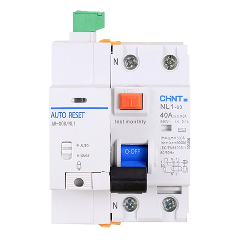
A Residual Current Circuit Breaker (RCCB) is a critical safety device designed to protect individuals and equipment from electrical hazards. It works by detecting an imbalance between the live and neutral wires, which typically indicates leakage current due to insulation failure or accidental contact with live parts. When such an imbalance is detected, the RCCB quickly disconnects the circuit, preventing electric shock and reducing the risk of electrical fires.
The AR-008/NL1 RCCB 2 pole with Auto Reset, manufactured by Zhejiang CHINT Electrics Co., Ltd., is a high-quality RCCB with an automatic reset feature, making it ideal for applications where uninterrupted power supply is critical.
Explore Projects Built with RCCB
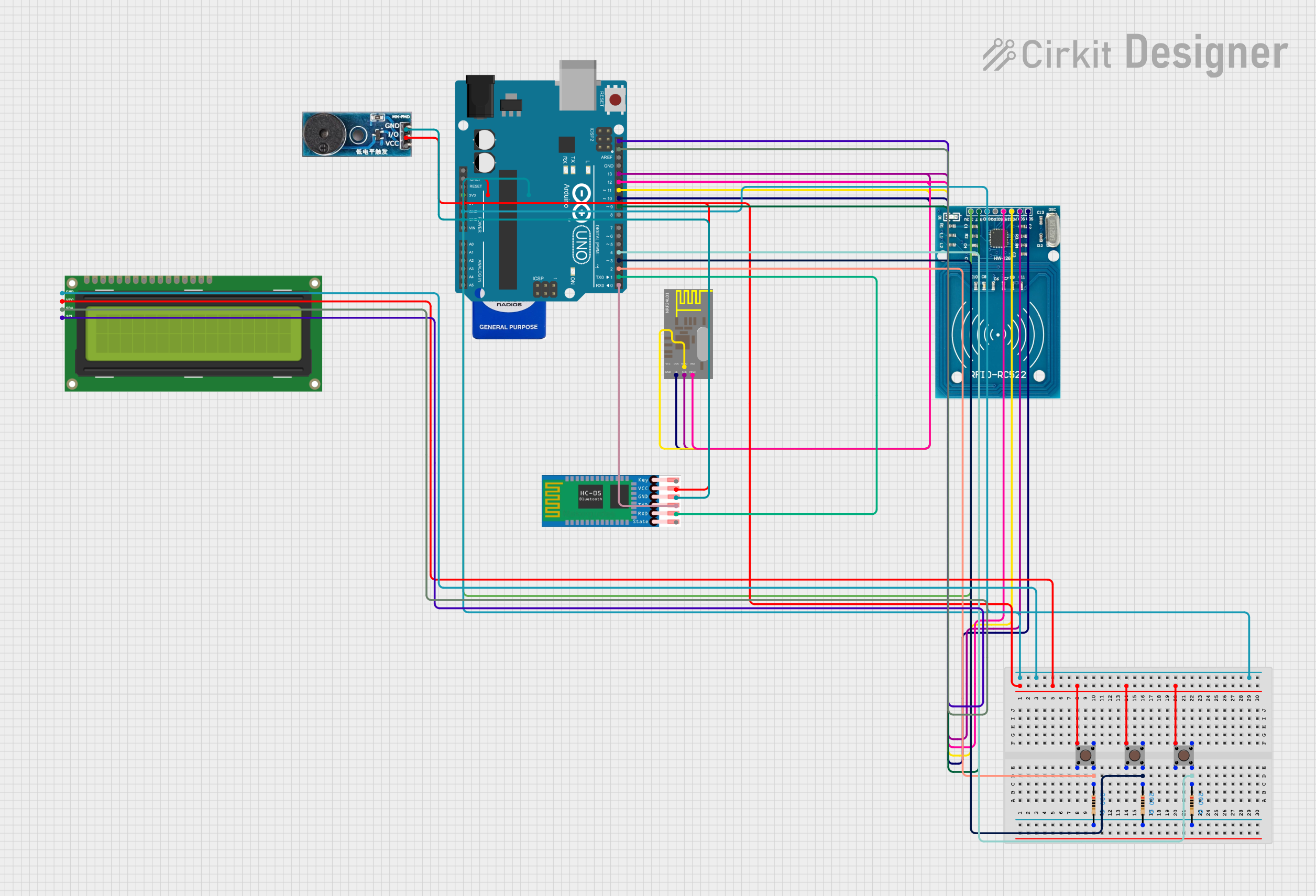
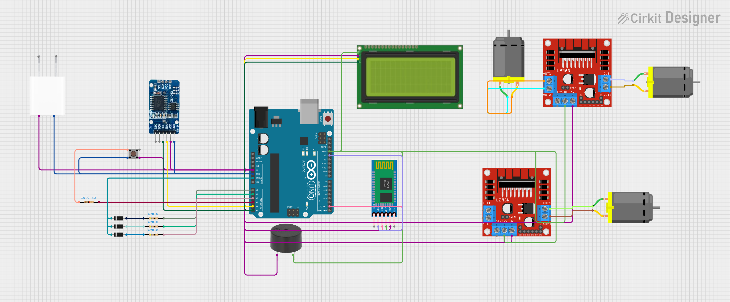
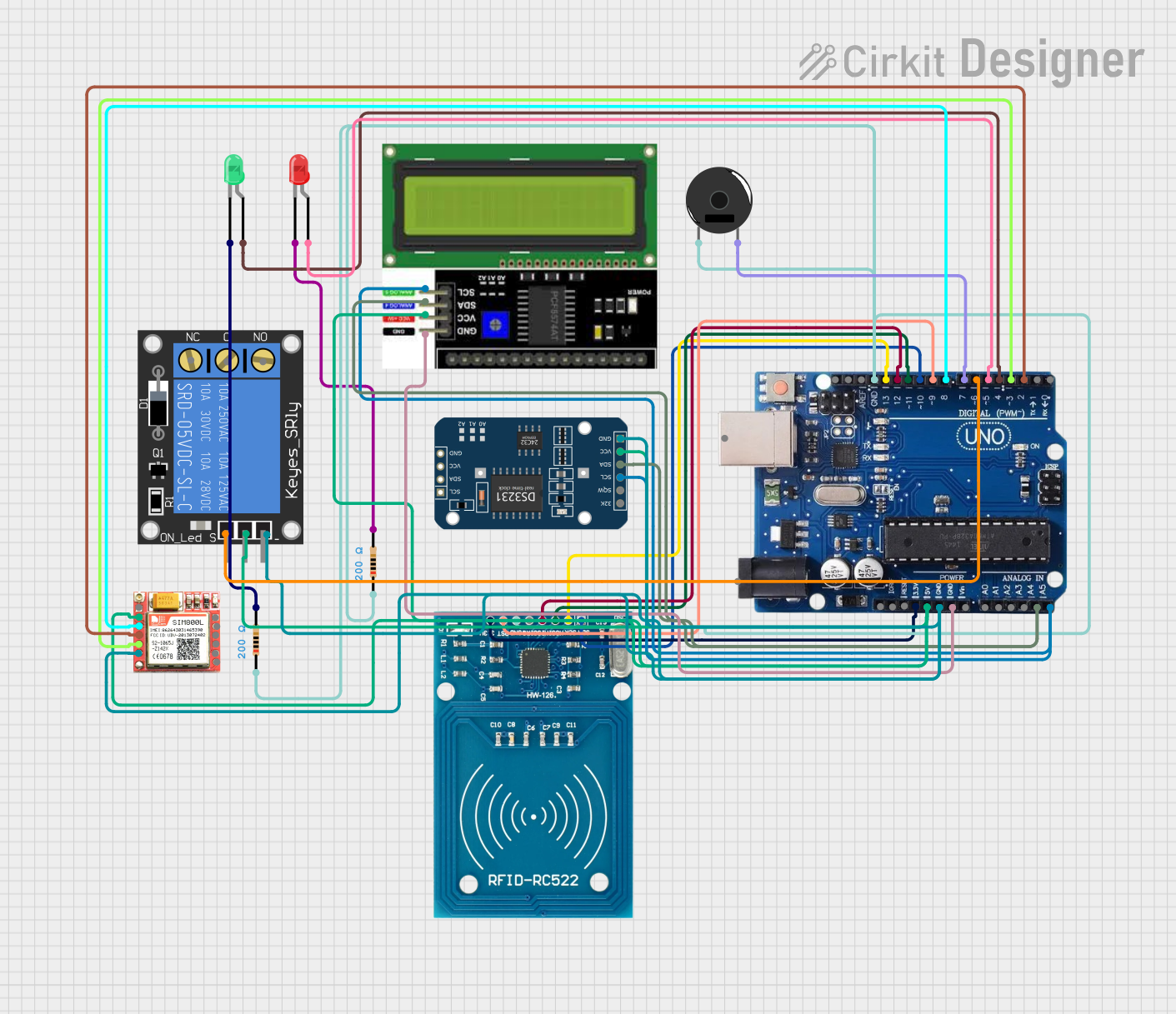
Explore Projects Built with RCCB
Common Applications
- Residential and commercial electrical systems
- Industrial equipment protection
- Data centers and server rooms
- Medical equipment and laboratories
- Outdoor installations prone to moisture or environmental hazards
Technical Specifications
Key Technical Details
| Parameter | Specification |
|---|---|
| Manufacturer | Zhejiang CHINT Electrics Co., Ltd. |
| Part Number | AR-008/NL1 RCCB 2 pole with Auto Reset |
| Number of Poles | 2 |
| Rated Voltage (Un) | 230V AC |
| Rated Current (In) | 8A |
| Rated Residual Current (IΔn) | 30mA |
| Frequency | 50/60 Hz |
| Operating Temperature Range | -25°C to +40°C |
| Reset Type | Automatic Reset |
| Mounting Type | DIN Rail |
| Compliance Standards | IEC 61008-1, IEC 61008-2-1 |
Pin Configuration and Descriptions
| Pin Number | Label | Description |
|---|---|---|
| 1 | L (Line) | Connect to the live input wire |
| 2 | N (Neutral) | Connect to the neutral input wire |
| 3 | L (Load) | Connect to the live output wire |
| 4 | N (Load) | Connect to the neutral output wire |
Usage Instructions
How to Use the RCCB in a Circuit
Preparation:
- Ensure the power supply is turned off before installation.
- Verify that the rated voltage and current of the RCCB match the circuit requirements.
Wiring:
- Connect the live input wire to the L (Line) terminal and the neutral input wire to the N (Neutral) terminal.
- Connect the live output wire to the L (Load) terminal and the neutral output wire to the N (Load) terminal.
- Ensure all connections are secure and properly insulated.
Testing:
- After installation, turn on the power supply.
- Press the Test Button on the RCCB to simulate a fault condition. The RCCB should trip immediately.
- If the RCCB does not trip, check the wiring and ensure the device is functioning correctly.
Operation:
- The RCCB will automatically reset after tripping if the fault condition is cleared.
- Regularly test the RCCB using the test button to ensure proper functionality.
Important Considerations and Best Practices
- Always follow local electrical codes and regulations during installation.
- Do not exceed the rated current or voltage of the RCCB.
- Avoid installing the RCCB in areas with excessive moisture or dust without proper enclosures.
- Periodically inspect the RCCB for signs of wear or damage.
- Use a compatible enclosure for outdoor installations to protect the RCCB from environmental factors.
Troubleshooting and FAQs
Common Issues and Solutions
| Issue | Possible Cause | Solution |
|---|---|---|
| RCCB does not trip during test | Faulty test button or internal failure | Replace the RCCB |
| RCCB trips frequently | Leakage current in the circuit | Inspect wiring and connected devices |
| RCCB does not reset | Persistent fault condition | Identify and fix the fault before resetting |
| RCCB trips without load | Incorrect wiring or insulation failure | Verify wiring and check for shorts |
FAQs
What is the purpose of the automatic reset feature?
The automatic reset feature ensures that the RCCB restores power automatically after a fault is cleared, minimizing downtime in critical applications.Can this RCCB be used in outdoor installations?
Yes, but it must be installed in a weatherproof enclosure to protect it from environmental factors.How often should the RCCB be tested?
It is recommended to test the RCCB using the test button at least once a month to ensure proper functionality.What happens if the RCCB trips but does not reset?
This indicates a persistent fault condition. Inspect the circuit for issues such as insulation failure or faulty devices before attempting to reset the RCCB.
This documentation provides a comprehensive guide to understanding, installing, and troubleshooting the AR-008/NL1 RCCB 2 pole with Auto Reset. Always prioritize safety and consult a licensed electrician for complex installations.