Cirkit Designer
Your all-in-one circuit design IDE
Home /
Component Documentation
How to Use Rotary encoder with button: Examples, Pinouts, and Specs
Introduction
A rotary encoder with an integrated push button is a versatile electronic component used to convert rotational position into an analog or digital signal. This component is widely used in various applications, including:
- User Interfaces: For navigating menus and adjusting settings in devices like audio equipment, industrial controls, and home appliances.
- Robotics: For precise control of motor positions and angles.
- Measurement Systems: For tracking rotational position and speed in machinery.
- Gaming: As input devices in custom game controllers.
Explore Projects Built with Rotary encoder with button
Arduino UNO-Based Rotary Encoder Interface
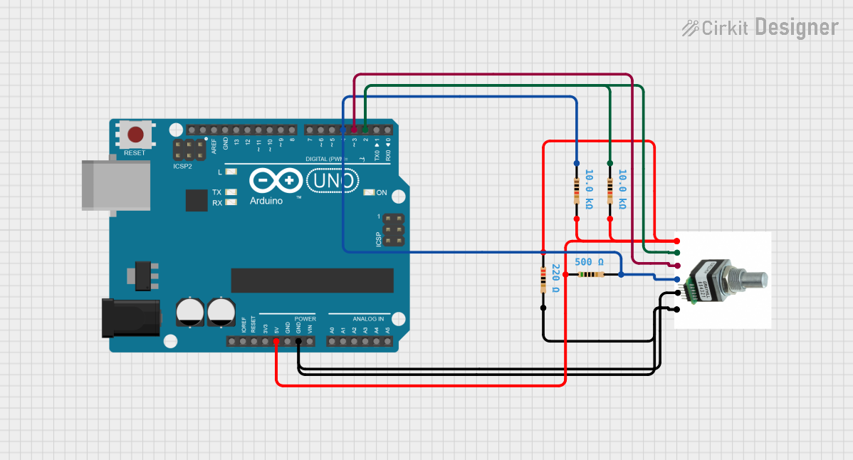
This circuit features a rotary encoder (로터리 엔코) interfaced with an Arduino UNO microcontroller. The encoder's outputs A and B are connected to digital pins D2 and D3 for rotation detection, while its push button is connected to D4, potentially for a user input function. The encoder, push button, and a switch are all debounced using resistors, and the microcontroller is set up to receive these signals for processing, although the provided code is empty and does not define specific behaviors.
Arduino Mega 2560-Based Rotary Encoder Control with Multiple Pushbuttons
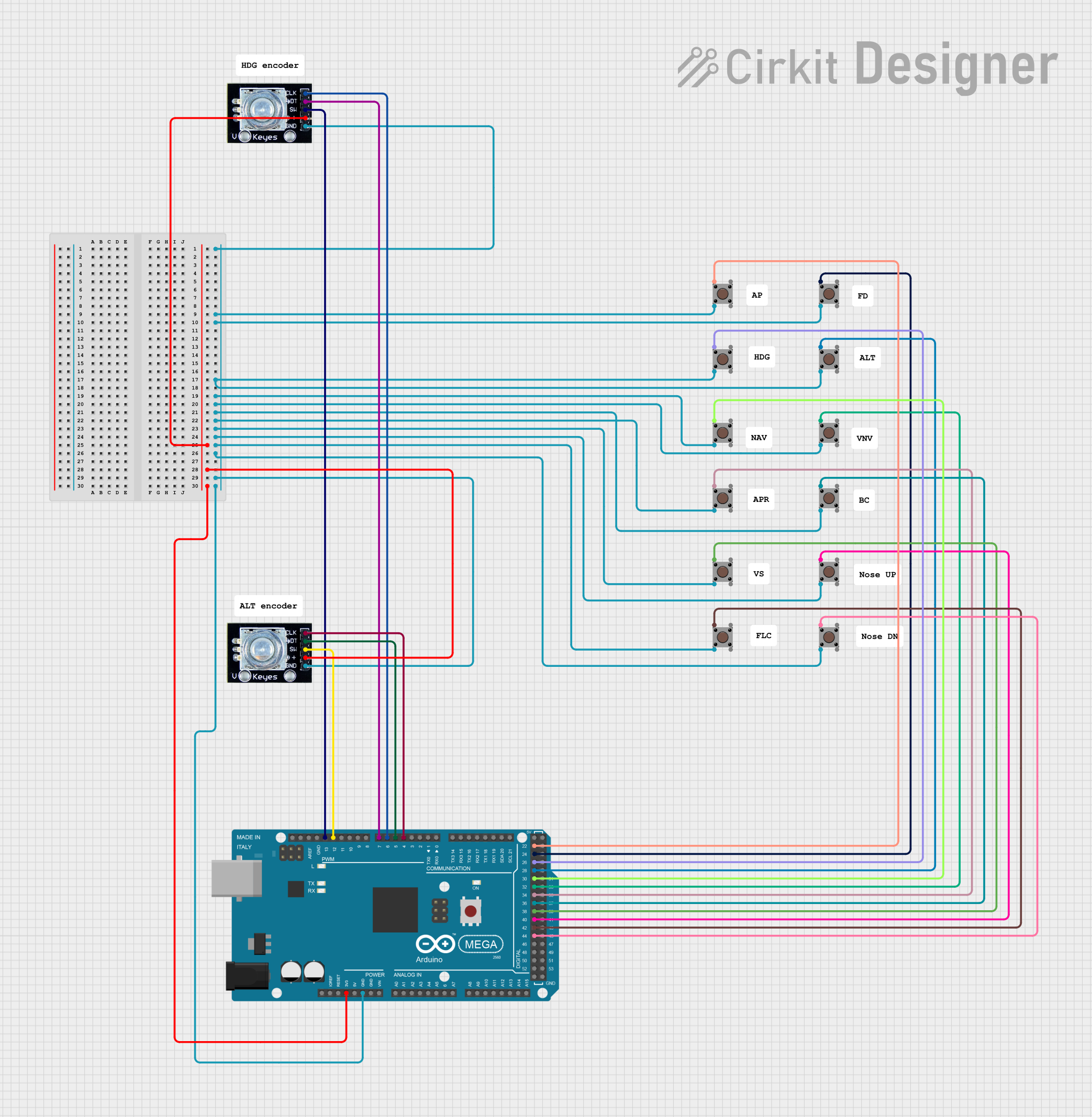
This circuit features an Arduino Mega 2560 microcontroller interfaced with multiple pushbuttons and rotary encoders, allowing for user input and control. The pushbuttons are connected to various digital pins on the Arduino, while the rotary encoders provide additional input through their clock and data signals, enabling precise adjustments and selections in the application.
Arduino UNO Rotary Encoder with I2C LCD Display
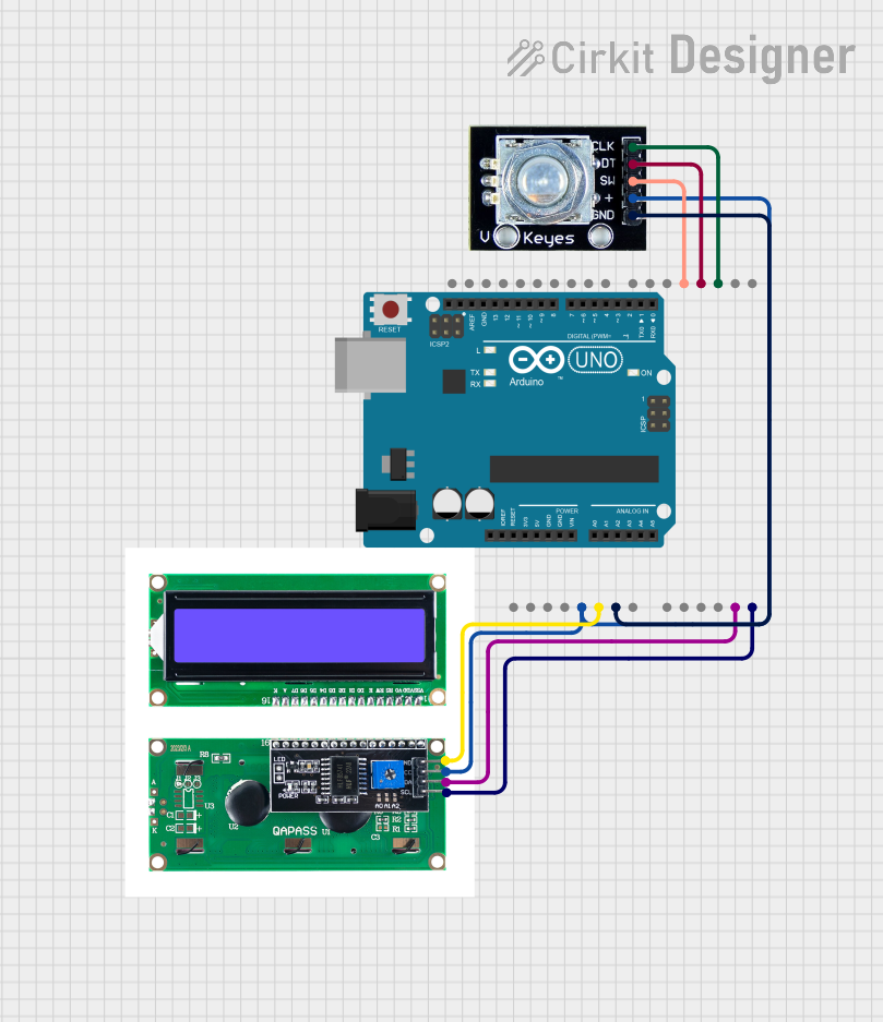
This circuit consists of an Arduino UNO microcontroller interfaced with an I2C LCD display and a rotary encoder. The Arduino reads the rotary encoder's position and button state, and communicates with the LCD display via I2C to show relevant information.
Raspberry Pi-Based Multi-Input Control System with Rotary Encoders and Proximity Sensor
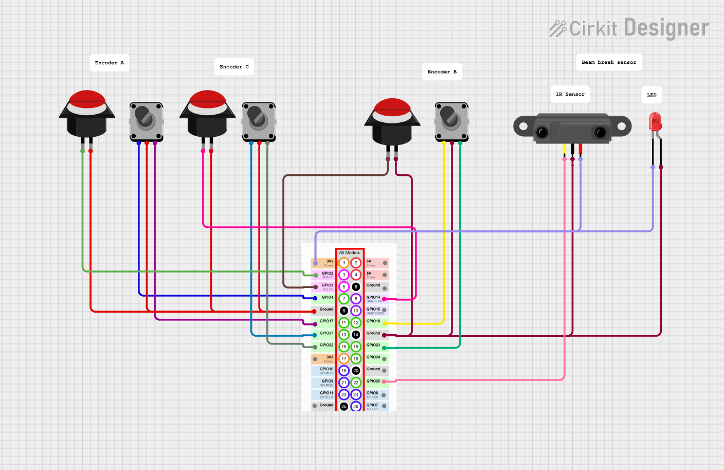
This circuit interfaces multiple rotary encoders, push buttons, an infrared proximity sensor, and an LED with a Raspberry Pi. The rotary encoders and push buttons provide user input, while the proximity sensor detects nearby objects and the LED indicates status, all managed through the GPIO pins of the Raspberry Pi.
Explore Projects Built with Rotary encoder with button
Arduino UNO-Based Rotary Encoder Interface
This circuit features a rotary encoder (로터리 엔코) interfaced with an Arduino UNO microcontroller. The encoder's outputs A and B are connected to digital pins D2 and D3 for rotation detection, while its push button is connected to D4, potentially for a user input function. The encoder, push button, and a switch are all debounced using resistors, and the microcontroller is set up to receive these signals for processing, although the provided code is empty and does not define specific behaviors.
Arduino Mega 2560-Based Rotary Encoder Control with Multiple Pushbuttons
This circuit features an Arduino Mega 2560 microcontroller interfaced with multiple pushbuttons and rotary encoders, allowing for user input and control. The pushbuttons are connected to various digital pins on the Arduino, while the rotary encoders provide additional input through their clock and data signals, enabling precise adjustments and selections in the application.
Arduino UNO Rotary Encoder with I2C LCD Display
This circuit consists of an Arduino UNO microcontroller interfaced with an I2C LCD display and a rotary encoder. The Arduino reads the rotary encoder's position and button state, and communicates with the LCD display via I2C to show relevant information.
Raspberry Pi-Based Multi-Input Control System with Rotary Encoders and Proximity Sensor
This circuit interfaces multiple rotary encoders, push buttons, an infrared proximity sensor, and an LED with a Raspberry Pi. The rotary encoders and push buttons provide user input, while the proximity sensor detects nearby objects and the LED indicates status, all managed through the GPIO pins of the Raspberry Pi.
Technical Specifications
Key Technical Details
| Parameter | Value |
|---|---|
| Operating Voltage | 3.3V to 5V |
| Maximum Current | 10mA |
| Output Type | Digital (Quadrature) |
| Push Button Rating | 10mA @ 5V |
| Rotational Steps | 20 steps per revolution |
| Debounce Time | 5ms (recommended) |
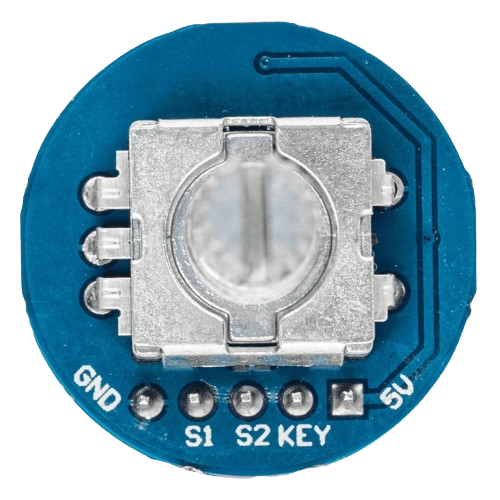
Pin Configuration and Descriptions
| Pin Number | Pin Name | Description |
|---|---|---|
| 1 | GND | Ground |
| 2 | +V | Supply Voltage (3.3V to 5V) |
| 3 | SW | Push Button Output |
| 4 | DT | Data Output (Quadrature Signal B) |
| 5 | CLK | Clock Output (Quadrature Signal A) |
Usage Instructions
How to Use the Component in a Circuit
Power Supply:
- Connect the
+Vpin to a 3.3V or 5V power supply. - Connect the
GNDpin to the ground of your circuit.
- Connect the
Rotary Encoder Outputs:
- Connect the
CLKpin to a digital input pin on your microcontroller. - Connect the
DTpin to another digital input pin on your microcontroller.
- Connect the
Push Button Output:
- Connect the
SWpin to a digital input pin on your microcontroller.
- Connect the
Important Considerations and Best Practices
- Debouncing: Rotary encoders can produce noisy signals. Implement software debouncing to ensure accurate readings.
- Pull-up Resistors: Use internal or external pull-up resistors for the
SW,CLK, andDTpins to ensure stable signals. - Interrupts: For real-time applications, consider using hardware interrupts to handle the encoder signals.
Example Code for Arduino UNO
// Rotary Encoder with Button Example Code for Arduino UNO

#define CLK 2  // Pin connected to CLK
#define DT 3   // Pin connected to DT
#define SW 4   // Pin connected to SW

int counter = 0;  // Counter to track encoder position
int currentStateCLK;
int lastStateCLK;
bool buttonPressed = false;

void setup() {
  pinMode(CLK, INPUT);
  pinMode(DT, INPUT);
  pinMode(SW, INPUT_PULLUP);  // Enable internal pull-up resistor

  // Read the initial state of CLK
  lastStateCLK = digitalRead(CLK);

  Serial.begin(9600);  // Initialize serial communication
}

void loop() {
  // Read the current state of CLK
  currentStateCLK = digitalRead(CLK);

  // If the state of CLK has changed, then we have a pulse
  if (currentStateCLK != lastStateCLK) {
    // If the DT state is different than the CLK state, then
    // the encoder is rotating counterclockwise
    if (digitalRead(DT) != currentStateCLK) {
      counter--;
    } else {
      // Encoder is rotating clockwise
      counter++;
    }

    Serial.print("Position: ");
    Serial.println(counter);
  }

  // Update the last state of CLK
  lastStateCLK = currentStateCLK;

  // Read the state of the push button
  if (digitalRead(SW) == LOW) {
    if (!buttonPressed) {
      Serial.println("Button Pressed");
      buttonPressed = true;
    }
  } else {
    buttonPressed = false;
  }
}
Troubleshooting and FAQs
Common Issues Users Might Face
Noisy Signals:
- Solution: Implement software debouncing to filter out noise.
Unstable Readings:
- Solution: Ensure proper pull-up resistors are used for the
SW,CLK, andDTpins.
- Solution: Ensure proper pull-up resistors are used for the
Incorrect Direction Detection:
- Solution: Verify the connections of the
CLKandDTpins. Ensure they are correctly mapped in the code.
- Solution: Verify the connections of the
Solutions and Tips for Troubleshooting
- Check Connections: Ensure all connections are secure and correctly mapped to the microcontroller pins.
- Use Serial Monitor: Utilize the Serial Monitor in Arduino IDE to debug and verify the encoder's output.
- Debounce Logic: Implement debounce logic in your code to handle noisy signals effectively.
By following this documentation, users can effectively integrate and utilize a rotary encoder with a button in their projects, ensuring accurate and reliable performance.