How to Use ESP32 38 PIN DEV MODULE: Examples, Pinouts, and Specs
Introduction
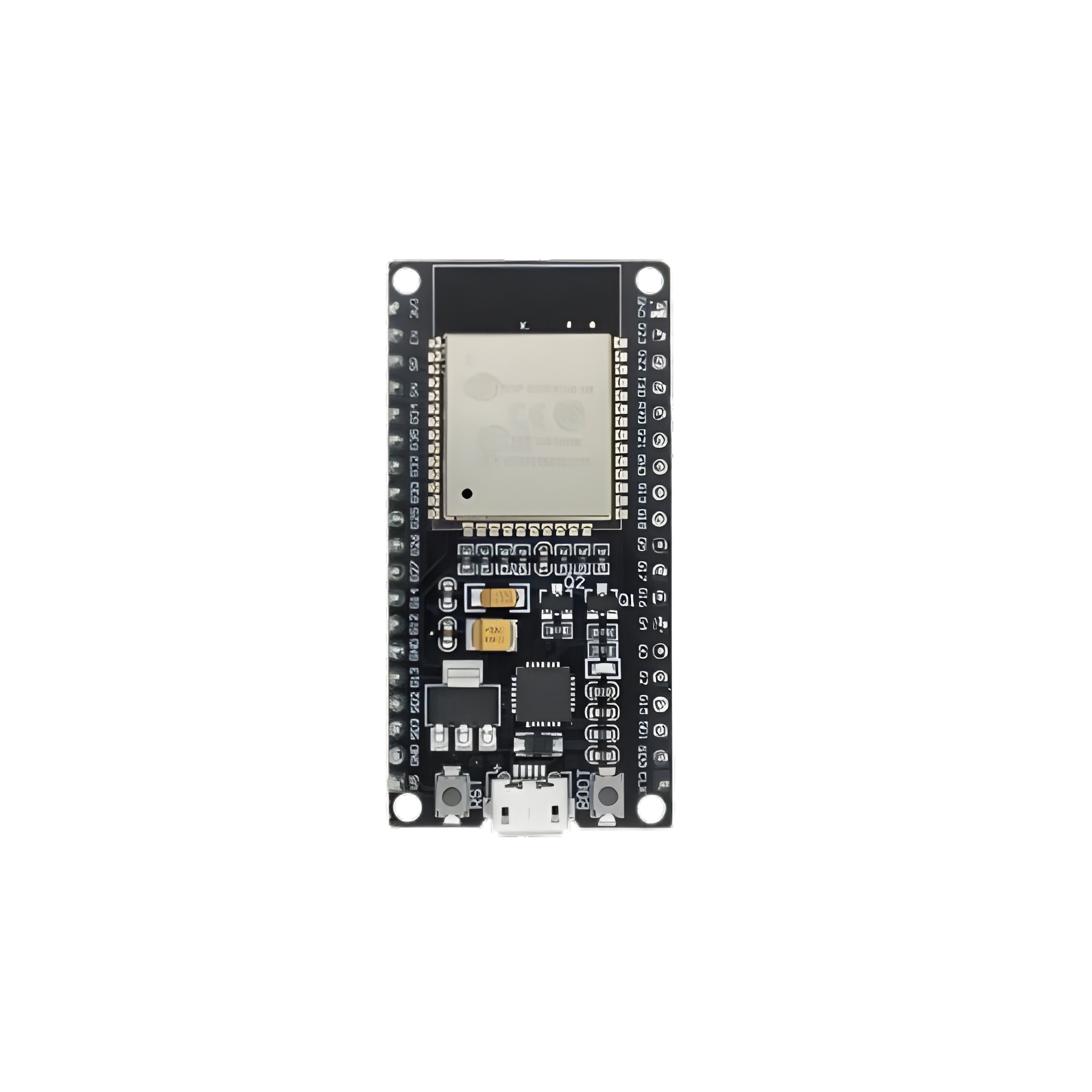
The ESP32 38 PIN DEV MODULE is a versatile development board featuring the ESP32 microcontroller. This microcontroller is equipped with integrated Wi-Fi and Bluetooth capabilities, making it an ideal choice for Internet of Things (IoT) projects and rapid prototyping. With 38 General Purpose Input/Output (GPIO) pins, the ESP32 module offers extensive connectivity options for various sensors, actuators, and other peripherals.
Explore Projects Built with ESP32 38 PIN DEV MODULE


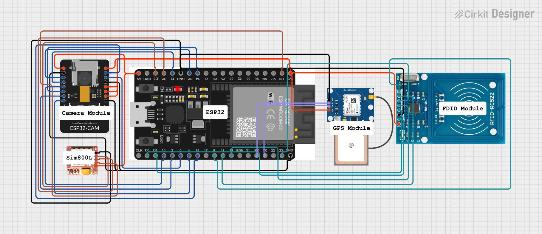

Explore Projects Built with ESP32 38 PIN DEV MODULE
Common Applications and Use Cases
- IoT Devices: Smart home automation, environmental monitoring, and wearable technology.
- Prototyping: Rapid development and testing of new electronic designs.
- Wireless Communication: Projects requiring Wi-Fi and Bluetooth connectivity.
- Embedded Systems: Integration into larger systems for enhanced functionality.
Technical Specifications
Key Technical Details
| Parameter | Value |
|---|---|
| Microcontroller | ESP32 |
| Operating Voltage | 3.3V |
| Input Voltage | 5V (via USB) or 7-12V (via Vin pin) |
| Digital I/O Pins | 38 |
| Analog Input Pins | 18 (ADC) |
| Analog Output Pins | 2 (DAC) |
| Flash Memory | 4MB |
| SRAM | 520KB |
| Wi-Fi | 802.11 b/g/n |
| Bluetooth | v4.2 BR/EDR and BLE |
| Clock Speed | 240 MHz (dual-core) |
| Power Consumption | 160 mA (average) |
Pin Configuration and Descriptions
| Pin Number | Pin Name | Description |
|---|---|---|
| 1 | EN | Enable (Active High) |
| 2 | IO36 | GPIO36, ADC1_CH0 |
| 3 | IO39 | GPIO39, ADC1_CH3 |
| 4 | IO34 | GPIO34, ADC1_CH6 |
| 5 | IO35 | GPIO35, ADC1_CH7 |
| 6 | IO32 | GPIO32, ADC1_CH4, Touch9 |
| 7 | IO33 | GPIO33, ADC1_CH5, Touch8 |
| 8 | IO25 | GPIO25, DAC1, ADC2_CH8 |
| 9 | IO26 | GPIO26, DAC2, ADC2_CH9 |
| 10 | IO27 | GPIO27, ADC2_CH7, Touch7 |
| 11 | IO14 | GPIO14, ADC2_CH6, Touch6, HSPI_CLK |
| 12 | IO12 | GPIO12, ADC2_CH5, Touch5, HSPI_Q |
| 13 | GND | Ground |
| 14 | IO13 | GPIO13, ADC2_CH4, Touch4, HSPI_ID |
| 15 | IO9 | GPIO9, ADC2_CH2, Touch2 |
| 16 | IO10 | GPIO10, ADC2_CH3, Touch3 |
| 17 | IO11 | GPIO11, ADC2_CH1, Touch1 |
| 18 | IO6 | GPIO6, ADC2_CH0, Touch0 |
| 19 | IO7 | GPIO7, ADC2_CH10, Touch10 |
| 20 | IO8 | GPIO8, ADC2_CH11, Touch11 |
| 21 | IO15 | GPIO15, ADC2_CH12, Touch12 |
| 22 | IO2 | GPIO2, ADC2_CH13, Touch13 |
| 23 | IO0 | GPIO0, ADC2_CH14, Touch14 |
| 24 | IO4 | GPIO4, ADC2_CH15, Touch15 |
| 25 | IO16 | GPIO16, ADC2_CH16, Touch16 |
| 26 | IO17 | GPIO17, ADC2_CH17, Touch17 |
| 27 | IO5 | GPIO5, ADC2_CH18, Touch18 |
| 28 | IO18 | GPIO18, ADC2_CH19, Touch19 |
| 29 | IO19 | GPIO19, ADC2_CH20, Touch20 |
| 30 | IO21 | GPIO21, ADC2_CH21, Touch21 |
| 31 | IO22 | GPIO22, ADC2_CH22, Touch22 |
| 32 | IO23 | GPIO23, ADC2_CH23, Touch23 |
| 33 | IO1 | GPIO1, ADC2_CH24, Touch24 |
| 34 | IO3 | GPIO3, ADC2_CH25, Touch25 |
| 35 | IO28 | GPIO28, ADC2_CH26, Touch26 |
| 36 | IO29 | GPIO29, ADC2_CH27, Touch27 |
| 37 | IO30 | GPIO30, ADC2_CH28, Touch28 |
| 38 | IO31 | GPIO31, ADC2_CH29, Touch29 |
Usage Instructions
How to Use the Component in a Circuit
Powering the ESP32:
- Connect the ESP32 to your computer using a USB cable for power and programming.
- Alternatively, supply 7-12V to the Vin pin for standalone operation.
Connecting to Peripherals:
- Use the GPIO pins to connect sensors, actuators, and other peripherals.
- Ensure that the peripherals operate at 3.3V logic levels to avoid damaging the ESP32.
Programming the ESP32:
- Install the Arduino IDE and add the ESP32 board support via the Board Manager.
- Select the appropriate ESP32 board from the Tools menu.
- Write your code and upload it to the ESP32 using the USB connection.
Important Considerations and Best Practices
- Voltage Levels: Ensure all connected devices operate at 3.3V logic levels.
- Power Supply: Use a stable power supply to avoid unexpected resets or malfunctions.
- Pin Multiplexing: Be aware that some pins have multiple functions (e.g., ADC, DAC, Touch). Check the datasheet for details.
- Wi-Fi and Bluetooth: Avoid using GPIO pins 1, 3, 9, 10, 11, and 12 for other purposes when using Wi-Fi or Bluetooth.
Example Code for Arduino IDE
#include <WiFi.h>

// Replace with your network credentials
const char* ssid = "your_SSID";
const char* password = "your_PASSWORD";

void setup() {
  Serial.begin(115200);

  // Connect to Wi-Fi
  WiFi.begin(ssid, password);

  // Wait for connection
  while (WiFi.status() != WL_CONNECTED) {
    delay(1000);
    Serial.println("Connecting to WiFi...");
  }

  Serial.println("Connected to WiFi");
}

void loop() {
  // Put your main code here, to run repeatedly
}
Troubleshooting and FAQs
Common Issues Users Might Face
ESP32 Not Connecting to Wi-Fi:
- Solution: Double-check the SSID and password. Ensure the Wi-Fi network is operational and within range.
ESP32 Not Detected by Computer:
- Solution: Ensure the USB cable is properly connected and functional. Try a different USB port or cable.
Random Resets or Crashes:
- Solution: Check the power supply for stability. Ensure peripherals are not drawing excessive current.
GPIO Pins Not Working:
- Solution: Verify the pin configuration in your code. Ensure no conflicts with other functions (e.g., ADC, DAC).
Solutions and Tips for Troubleshooting
- Serial Monitor: Use the Serial Monitor in the Arduino IDE to print debug messages and monitor the ESP32's status.
- Firmware Updates: Ensure the ESP32 has the latest firmware and libraries installed.
- Community Support: Utilize online forums and communities for additional support and troubleshooting tips.
By following this documentation, users can effectively utilize the ESP32 38 PIN DEV MODULE for a wide range of applications, from simple prototypes to complex IoT systems.