How to Use ESP8266 ESP-03 WiFi Module: Examples, Pinouts, and Specs
Introduction
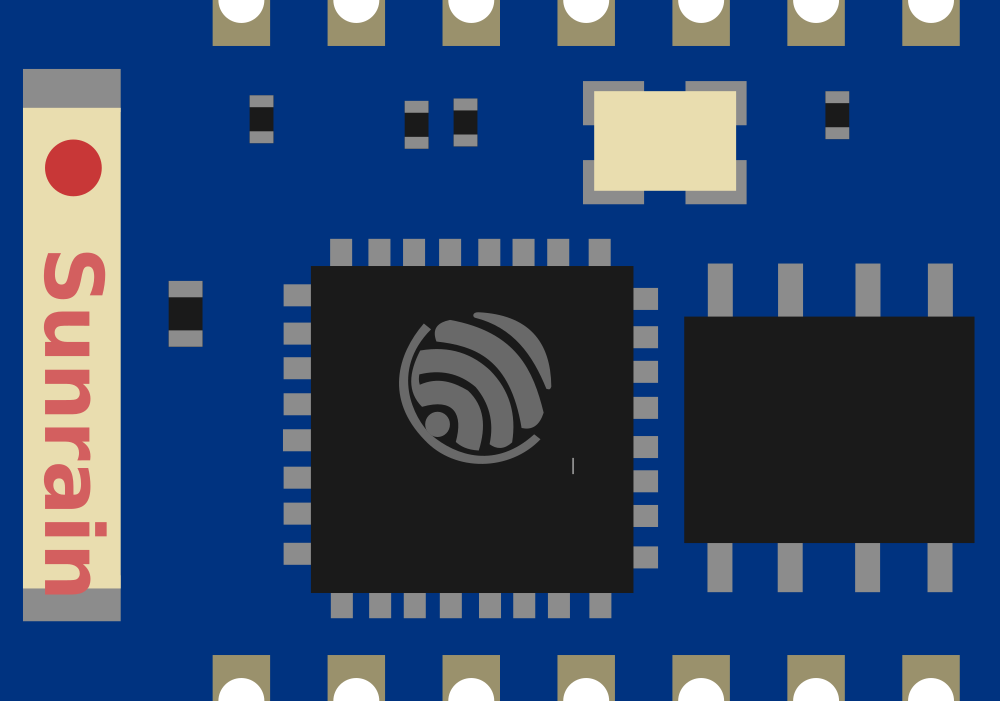
The ESP8266 ESP-03 WiFi Module is a self-contained wireless networking solution that offers a combination of versatility, reliability, and cost-effectiveness. Based on the popular ESP8266 chipset, the ESP-03 module provides WiFi connectivity along with a powerful on-chip microcontroller, enabling users to develop Internet of Things (IoT) applications with ease. Its compact form factor and integrated antenna make it ideal for space-constrained projects. Common applications include home automation, sensor networks, and wireless data logging.
Explore Projects Built with ESP8266 ESP-03 WiFi Module


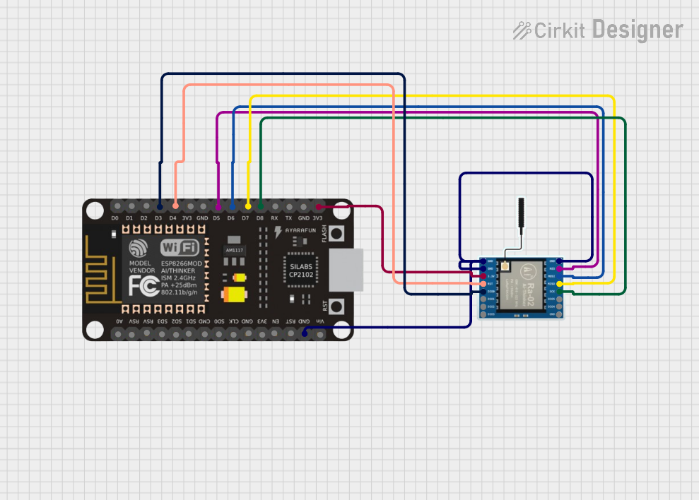
Explore Projects Built with ESP8266 ESP-03 WiFi Module
Technical Specifications
General Features
- Integrated TCP/IP protocol stack
- WiFi Direct (P2P), soft-AP
- Integrated low power 32-bit CPU, which can also serve as an application processor
- SDIO 1.1 / 2.0, SPI, UART
- STBC, 1x1 MIMO, 2x1 MIMO
- A-MPDU & A-MSDU aggregation & 0.4ms guard interval
- Wake up and transmit packets in < 2ms
- Standby power consumption of < 1.0mW (DTIM3)
Electrical Characteristics
- Power Supply: 3.3V
- Current Consumption: Average ~80mA
- Operating Temperature Range: -40°C to 125°C
Pin Configuration and Descriptions
| Pin Number | Name | Description |
|---|---|---|
| 1 | GND | Ground |
| 2 | GPIO0 | General Purpose I/O 0 |
| 3 | GPIO2 | General Purpose I/O 2 |
| 4 | RX | UART Receive Pin |
| 5 | TX | UART Transmit Pin |
| 6 | CH_PD | Chip Power-Down Pin |
| 7 | RST | Reset Pin |
| 8 | VCC | 3.3V Power Supply |
Usage Instructions
Integrating with a Circuit
Power Supply: Ensure that the module is powered with a stable 3.3V supply. Exceeding the voltage rating can damage the module.
Serial Communication: Connect the RX and TX pins to a serial converter or microcontroller to enable UART communication.
GPIO Pins: GPIO0 and GPIO2 can be used for custom functions, but note that GPIO0 must be low during power-up to enter flash mode.
Reset and Chip Enable: The RST pin can be used to reset the module. The CH_PD pin must be pulled high to enable the chip.
Best Practices
- Use a high-quality 3.3V voltage regulator to avoid power supply issues.
- Ensure proper antenna placement and orientation for optimal wireless performance.
- Avoid placing the module near metal objects or surfaces that may interfere with signal propagation.
- Implement proper ESD precautions when handling the module to prevent damage.
Example Code for Arduino UNO
#include <ESP8266WiFi.h>

// Replace with your network credentials
const char* ssid = "your_SSID";
const char* password = "your_PASSWORD";

void setup() {
  Serial.begin(115200); // Start serial communication at 115200 baud
  WiFi.begin(ssid, password); // Connect to the WiFi network

  while (WiFi.status() != WL_CONNECTED) { // Wait for connection
    delay(500);
    Serial.print(".");
  }

  Serial.println("");
  Serial.println("WiFi connected");
}

void loop() {
  // Put your main code here, to run repeatedly:
}
Troubleshooting and FAQs
Common Issues
- Module Does Not Power On: Check the power supply and connections to ensure the module is receiving 3.3V.
- Cannot Connect to WiFi: Verify the SSID and password are correct. Ensure the module is within range of the router.
- Serial Communication Failure: Ensure that the baud rate of the module matches the baud rate set in your microcontroller's UART settings.
FAQs
Q: Can the ESP-03 module be used with a 5V power supply? A: No, the ESP-03 requires a 3.3V power supply. Using a 5V supply can permanently damage the module.
Q: How can I improve the WiFi range of the ESP-03 module? A: Ensure that the antenna is properly oriented and placed away from metal objects. Additionally, consider using an external antenna if your design allows for it.
Q: What is the maximum number of GPIO pins available on the ESP-03? A: The ESP-03 provides access to two GPIO pins, GPIO0 and GPIO2.
Q: How do I flash new firmware onto the ESP-03? A: To flash firmware, GPIO0 must be held low during power-up to enter flash mode. Use a serial-to-USB converter to upload the firmware via the UART interface.
This documentation provides an overview of the ESP8266 ESP-03 WiFi Module, its technical specifications, usage instructions, example code for Arduino UNO, and troubleshooting tips. For more detailed information, refer to the manufacturer's datasheets and user guides.