How to Use TIP41C: Examples, Pinouts, and Specs
Introduction
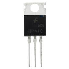
The TIP41C is a versatile NPN power transistor designed for use in power amplification and switching applications. Manufactured by Abhishek, this component is widely used in a variety of electronic circuits due to its high power dissipation capabilities and robust performance. Common applications include audio amplifiers, power regulators, and motor control circuits.
Explore Projects Built with TIP41C
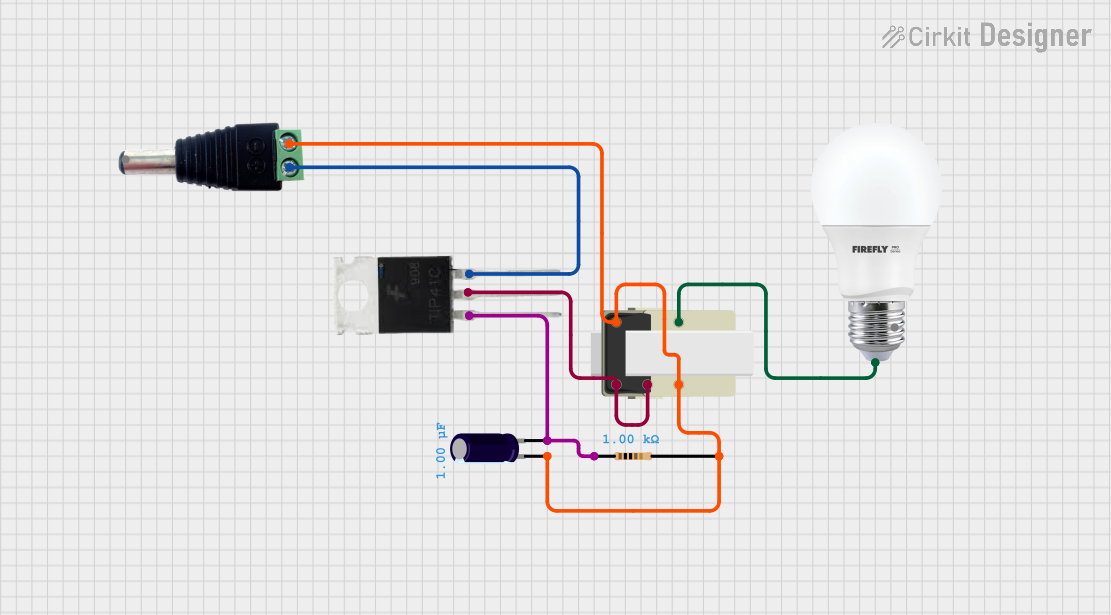
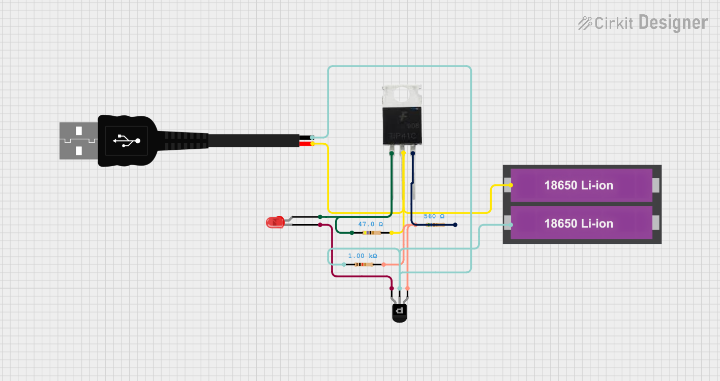
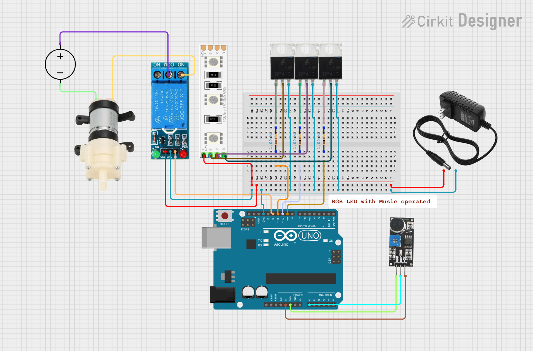

Explore Projects Built with TIP41C
Technical Specifications
General Characteristics
- Type: NPN Bipolar Power Transistor
- Maximum Collector-Emitter Voltage (Vce): 100 V
- Maximum Collector-Base Voltage (Vcb): 100 V
- Maximum Emitter-Base Voltage (Veb): 5 V
- Maximum Collector Current (Ic): 6 A
- Power Dissipation (Pd): 65 W
- Operating Junction Temperature (Tj): -65 to 150°C
Pin Configuration and Descriptions
| Pin Number | Name | Description |
|---|---|---|
| 1 | Base | The control terminal through which the transistor is biased and controlled. |
| 2 | Collector | The terminal through which the main current flows from collector to emitter. |
| 3 | Emitter | The terminal through which the main current exits the transistor. |
Usage Instructions
Incorporating the TIP41C into a Circuit
To use the TIP41C in a circuit:
- Biasing the Transistor: Apply a voltage to the base relative to the emitter to control the current flow from the collector to the emitter.
- Load Connection: Connect the load to be controlled or powered between the collector and the power supply.
- Emitter Connection: Connect the emitter to the ground or negative side of the power supply.
Best Practices
- Ensure that the voltage and current ratings are not exceeded to prevent damage.
- Use a suitable base resistor to limit the base current and protect the transistor.
- Implement a heatsink if the transistor is expected to dissipate significant power.
- Provide adequate ventilation around the transistor to prevent overheating.
Example Circuit: Driving a Motor with Arduino UNO
// Motor control using TIP41C and Arduino UNO

const int motorPin = 9; // Connect to the base of TIP41C

void setup() {
  pinMode(motorPin, OUTPUT); // Set motor pin as output
}

void loop() {
  analogWrite(motorPin, 128); // Set speed to approximately 50%
  delay(2000);                // Run the motor for 2 seconds
  analogWrite(motorPin, 0);   // Turn off the motor
  delay(2000);                // Wait for 2 seconds
}
Note: Ensure that the motor current does not exceed the TIP41C's maximum collector current rating.
Troubleshooting and FAQs
Common Issues
- Motor not running: Check if the base is receiving the correct bias voltage.
- Transistor overheating: Verify that the power dissipation is within limits and that a heatsink is properly installed.
- Unexpected shutdown: Ensure that the maximum voltage and current ratings are not exceeded.
FAQs
Q: Can the TIP41C be used for AC power applications? A: No, the TIP41C is designed for DC applications.
Q: What is the function of the base resistor? A: The base resistor limits the base current to prevent damage to the transistor.
Q: How can I increase the current handling capability? A: You can parallel multiple TIP41C transistors, ensuring equal current sharing with emitter resistors.
For further assistance, please refer to the manufacturer's datasheet or contact technical support.